Facebook
 Google
 GitHub
 Linkedin
Hi to all.
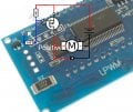
I need a positive PWM wave to control battery charger of an electric vehicle.
I've bought this.
the problem is that the positive is permanent and the negative follows the frequency and duty cycles that i choose.
i would like that the PWM will be on the positive.
I need a positive PWM wave to control battery charger of an electric vehicle.
I've bought this.
the problem is that the positive is permanent and the negative follows the frequency and duty cycles that i choose.
i would like that the PWM will be on the positive.