Need to understand the function of the circuit

Thread Starter

Electronic_Maniac

Joined Oct 26, 2017
253
Hi all,

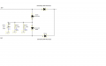
Can someone clearly explain the function of the circuit. It has been said that it is for protection during reverse transients.
But I dont understand how that value of capacitor and resistor is arrived at. The 2 rectifier diodes are rated for 400V negative transients.

Can someone please help me understand.

The input voltage at the two lines is the same 16V.

Thanks.
 

Attachments

Alec_t

Joined Sep 17, 2013
14,280
If a transient causes either 16V rail to go negative with respect to circuit common then D100 or D101 will conduct and the cap will start to charge, absorbing the transient's energy. After the transient the cap discharges via R122 and R124. The cap capacity and breakdown values and resistor values would need to be chosen according to the expected transient magnitude, duration and frequency of occurrence. Ideally the cap should not charge fully but should discharge completely between transients.
 

kubeek

Joined Sep 20, 2005
5,794
I guess the answer very much depends on what kind of reverse transient you need to protect against. A typical normative surge into power supply is 1kV impulse coupled with a 9uF capacitor IIRC. That would charge your capacitor to about 19V, and then later discharge that energy into the resistors.
 

Thread Starter

Electronic_Maniac

Joined Oct 26, 2017
253
If a transient causes either 16V rail to go negative with respect to circuit common then D100 or D101 will conduct and the cap will start to charge, absorbing the transient's energy. After the transient the cap discharges via R122 and R124. The cap capacity and breakdown values and resistor values would need to be chosen according to the expected transient magnitude, duration and frequency of occurrence. Ideally the cap should not charge fully but should discharge completely between transients.
Thanks. The transient magnitude would be 4kV to 6kV. Another doubt which I had was why would we need to have an electrolytic capacitor positive terminal connected to ground? I understand that since it is an electrolytic cap, we cannot have the positive terminal on the top during negative transients which would blow the cap off.
So, my doubt is that why an electrolytic cap and not a ceramic one? And Doesn't the positive terminal of the cap connected to the circuit ground, destroy the cap ? If we are concerned about only the voltage, how do you choose a capacitor based on its value? For ex. how do we decide between 330uF 25V cap and 470uF 25V cap? Both have the same voltage rating. But which one to choose (capacitance value consideration)?
 

Thread Starter

Electronic_Maniac

Joined Oct 26, 2017
253
I guess the answer very much depends on what kind of reverse transient you need to protect against. A typical normative surge into power supply is 1kV impulse coupled with a 9uF capacitor IIRC. That would charge your capacitor to about 19V, and then later discharge that energy into the resistors.
Thanks. Can you tell me how did you arrive at the value of 19V at the cap with your numbers? Can you please explain me the calculation?
 

kubeek

Joined Sep 20, 2005
5,794
You cannot get a 470uF 25V ceramic capacitor as far as I know. A film one would be huge.
I arrived at the value by calculating a simple capacitive divider, 9uF/(470+9uF)*1kV~=19V.
What standard is that, which requires 4-6kV surge applied to the power supply? And what happens when the surge is of positive amplitude? Anyway my guess is that the final value was arrived at by trial and error, rather than some exact calculation.
 

Thread Starter

Electronic_Maniac

Joined Oct 26, 2017
253
You cannot get a 470uF 25V ceramic capacitor as far as I know. A film one would be huge.
I arrived at the value by calculating a simple capacitive divider, 9uF/(470+9uF)*1kV~=19V.
What standard is that, which requires 4-6kV surge applied to the power supply? And what happens when the surge is of positive amplitude? Anyway my guess is that the final value was arrived at by trial and error, rather than some exact calculation.
Thanks. This is some test which I have to carry out. I need to apply 4-6kV for 100ms at 1 min interval and check my Board for any malfunction. I planned to understand the design first.
 

Alec_t

Joined Sep 17, 2013
14,280
And Doesn't the positive terminal of the cap connected to the circuit ground, destroy the cap ?
No, because D100 and D101 prevent positive transients from reverse-charging the cap.
This is some test which I have to carry out. I need to apply 4-6kV for 100ms at 1 min interval and check my Board for any malfunction.
What is the source impedance of this voltage? Unless it's high I doubt you will be left with a board to check :eek:. You will probably destroy the cap, the resistors, the Schottky diodes and whatever is connected to those.
 
Last edited:

kubeek

Joined Sep 20, 2005
5,794
4kV will destroy evertyhing, unless the current or stored energy is somehow limited, which you dont say. The diodes that charge the cap are only 400V, so the will get blown. The schottkys as well, and also if you apply the posive 4kV it will go straight into the rest of the circuit.
 

Thread Starter

Electronic_Maniac

Joined Oct 26, 2017
253
4kV will destroy evertyhing, unless the current or stored energy is somehow limited, which you dont say. The diodes that charge the cap are only 400V, so the will get blown. The schottkys as well, and also if you apply the posive 4kV it will go straight into the rest of the circuit.
its both +ve and -ve 4kV for microsec duration
 

Alec_t

Joined Sep 17, 2013
14,280
Can you please explain clearly in simple terms
Since the cap's +ve terminal is connected to circuit ground, the cap would become damaged if reverse-charged, i.e. if its -ve terminal were raised above ground by a positive transient exceeding the breakdown voltage of D100/101.
its both +ve and -ve 4kV for microsec duration
Well, that's a lot different from what you said originally :rolleyes:.
I suspect, though, that real transients might well exceed the 1uS duration.
Your circuit can't provide any protection against +4kV.
 

kubeek

Joined Sep 20, 2005
5,794
Standard suge impulses according to IEC61000-4-5 are 1.2/50us rise and fall time, or 10/700us. At 4kV you can expect peak currents on the order of 2kA.
I have a strong suspicion that your 4-6kV test is of a completely different nature, possible from an ESD gun which is much shorter and much lower in energy.
 

ebp

Joined Feb 8, 2018
2,332
It is a weird circuit.

An aluminum electrolytic capacitor is completely unsuitable for controlling fast high amplitude transients due to its inductance and equivalent series resistance (ESR). If you put a fast spike of several hundred volts negative on either of those lines, the Schottky diodes would almost certainly break down. A transient with a slow transition from a source with adequately high impedance might be adequately "eaten" by the electrolytic capacitor. Normally for transient protection you try to play the impedance of one component against that of another, for example a series resistance or inductive reactance against a shunting capacitance or semiconductor device. Even with ideal components, physical layout of such a circuit is critical to performance.

Nothing in that circuit will do anything to control positive transients until they are of sufficient magnitude to cause reverse breakdown of D10x, and then the problem of the performance of the electrolytic capacitor still remains - and it has reverse polarity applied.

What is the function of the 16 volt lines? Are they power supplies or signals?
 

BillB3857

Joined Feb 28, 2009
2,570
I am obviously missing something, which isn't too unusual. Don't the 4 diodes make a bridge circuit? The anode junction would create a negative voltage, which is properly applied to the cap and the two resistors would act as current limit for the output and bleeder for the cap. Without seeing the source, other than the label (16v) and some indication as to what the load is I'm pretty well in the dark. Where is the 4-6KV coming from? How is it tied to this circuit?
 
Top