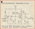
Need to boost microphone input to my audio tape recorder

Thread Starter

rameshdk12

Joined Aug 20, 2024
11
Cheap digital recordings that have been recorded on commercial and not professional equipment also would suffer the same problem. Also I wonder how the sampling noise and quantization noise are taken care of in digitizing the signal. While quantizing each sample of the signal a few bits are inaccurate which leads to noise in every one of the samples of the digital signal . The reverse D to A conversion also requires high quality to reproduce the original. How do you smooth out the difference between samples?,then again there is compression of the music into mp3 format.
There used to be a time in the analog days when cheap boom boxes would dominate the market though they sounded better than the mobile phones or laptop speakers. In the digital era also cheap boxes are dominating. For the common man high fidelity is not in reach. I may be partially wrong but that's my intuition and I have a liking for analog .
 

LowQCab

Joined Nov 6, 2012
5,101
Cheap digital recordings that have been recorded on commercial and not professional equipment also would suffer the same problem. Also I wonder how the sampling noise and quantization noise are taken care of in digitizing the signal. While quantizing each sample of the signal a few bits are inaccurate which leads to noise in every one of the samples of the digital signal . The reverse D to A conversion also requires high quality to reproduce the original. How do you smooth out the difference between samples?,then again there is compression of the music into mp3 format.
There used to be a time in the analog days when cheap boom boxes would dominate the market though they sounded better than the mobile phones or laptop speakers. In the digital era also cheap boxes are dominating. For the common man high fidelity is not in reach. I may be partially wrong but that's my intuition and I have a liking for analog .
.
A to D, and D to A, Converters have gotten so good that it's almost impossible to measure them,
even the cheap ones.

There will always be a few nuts out there that will claim they can hear the difference,
but they can't pass a blind A-B test on their best day.

There are far more important factors that get completely ignored,
like the listening-room-treatment, and the fact that the
best Speakers in the world still have about ~3% THD, and this includes Headphones too.
And "most" "Hi-Fi" Speakers have in excess of ~10% Distortion.

The real question is, does the equipment provide a pleasant experience ?,
The "Audiofools" claim that it couldn't possibly,
I guess because it isn't expensive enough,
and there's too much Oxygen in the Copper-Circuit-Board-Traces !!!
I guess it takes all types of people to make the World go 'round,
but I'm particularly picky about which ones I'll take any advice from,
and I think You should too.
.
.
.
 

AnalogKid

Joined Aug 1, 2013
12,238
The mathematical descriptions of A/D and D/A quantizing errors have been around since the 1940's (with roots to 1807), and circuits to implement both the converters and the corrections have been in continuous development since the 1970's. That's a looong time in EE years, and the results are pretty good.

ak
 

MisterBill2

Joined Jan 23, 2018
28,031
Background noise is seldom welcome, and when avoiding it is so simple, why not?? And just because some folks are always aware of that alleged tape hiss, others of us seem to do very well not noticing it. It would be most obvious in the quiet portions of the recording. And silence is seldom why we listen to a recording.
 

sparky 1

Joined Nov 3, 2018
1,218
ttempting to Don't know the model, Fisher PH 415 manual. The specs calls for MIC has impedance Z= 3.3k
Compared to a 600 Ohm MIC, 3.3k is deemed high impedance. Possibly term high impedance changed it's meaning over time.
An electret possibly? the proof in this is during testing, possibly you will prefer to modify it higher of lower.
Fisher PH 415 K Service Manual : Fisher Corporation : Free Download, Borrow, and Streaming : Internet Archive
If an audio signal connected to the pre amp circuit. It could be terminated with 3.3k resistor RL the measured
voltage in RMS would be half of the output voltage of the circuit not terminated. Hopefully I have that correct.

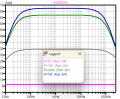
The one transistor circuit might be alright but the simulation numbers show that the gain would be just little shy.
To raise the gain is easy, however the high % THD does not go away with frequency response test. Op Amps like OPA322
were recommended for new design and supply diminished, I found a Calrad DT 50k

The Fisher design would benefit from a MIC with much higher impedance in order to use a single transistor
when RL is 10K. OK. A simulation shows that you need the correct microphone or higher gain without poor THD.
If you have a large inventory of microphone elements then you need to use what you have. The cassette recorder consumers
would need to upgrade to the revised smaller cassette with higher impedance electret.

The distorsion analysis using the best low noise transistors will work but the output is not the best quality.
Does LTSpice check SINAD and THD? Am I missing something? Does distortion just disappear?
Forrest Mimms is ok for getting started but there is a noticeable difference or maybe a restoration is just not worth the expense.
Without coming back with the much needed specs it is too difficult to go much further than what is being offered.
Below need to switch R1 with R5 and the output load of 50K. The TSB-165A was popular with 2N4416 along with second stage.
TSB-165A and External FETs (mp3forkidz.com)

Forrest Mimms amplifier.png
 
Last edited:

MisterBill2

Joined Jan 23, 2018
28,031
"Optimum Power Transfer" has not seemed to be a major consideration in the lower level audio circuits I have deal with. Noise, distortion, and frequency response are much more important most of the time, because usually a bit of extra gain is fairly low cost in those low level circuits.
Consider that the main benefits of the very low impedance balanced microphone scheme are better frequency response, (because of the lower effect of cable shunt capacitance at lower impedance), and reduced noise pickup.
 

MisterBill2

Joined Jan 23, 2018
28,031
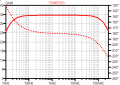
If I am reading the plot of the output correctly, it is a unity-gain amplifier, which may possibly improve an impedance match while not providing any useful gain.
So either I do not understand the graphics or there is no benefit provided by a unity gain circuit. So an explanation is in order.
 

MrChips

Joined Oct 2, 2009
35,023
If I am reading the plot of the output correctly, it is a unity-gain amplifier, which may possibly improve an impedance match while not providing any useful gain.
So either I do not understand the graphics or there is no benefit provided by a unity gain circuit. So an explanation is in order.
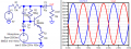
Look at the top of the graph where it says V(in)*34.5, i.e. the gain is 34.5.
Also in the bode plot, the scale on the left hand side shows a gain of 35.

The simulator I used gave a gain of 60.
 

Thread Starter

rameshdk12

Joined Aug 20, 2024
11
I am looking into some very good advice given by AnalogKid. The SSM series opamps by analog devices look as a very good choice ,but they seem to require additional power supply of 48v(+/-24v).Is this true if we use dynamic microphones?.Going back to my 741 opamp circuit i will add the filter capacitor for the low and high frequencies as suggested and also 0.1uf at the power supply, Also I will be testing with different input resistor values of the circuit(the resistance that the mike sees ) .
Thank You All
 

eetech00

Joined Jun 8, 2013
4,724
If its a balanced dynamic microphone, you can use an single instrumentation amp (differential input), and get good gain and noise cancellation. Look at INA126. Shure dynamic microphone output impedence is typically 300 ohms.
 

eetech00

Joined Jun 8, 2013
4,724
Thanks very much for both replies.
I am using a mic that is made by philips(quite old) and is of moving coil i.e dynamic type.
The casette recorder is made by FISHER (made in china)
How much input and output impedance should my preamplifier have to match the mic input on the tape recorder,
and how can I design for that. will Changing the opamp improve my gain also. I tried adding another opamp stage but it degraded the output
I checked on my headphones.
Can you post a picture of the microphone? with p/n visible if possible.
 

AnalogKid

Joined Aug 1, 2013
12,238
I am looking into some very good advice given by AnalogKid. The SSM series opamps by analog devices look as a very good choice ,but they seem to require additional power supply of 48v(+/-24v).Is this true if we use dynamic microphones?
While some microphone preamp IC's might be able to run on those voltages, I don't know of any that *require* them. You might be confusing a preamp circuit with a phantom power circuit. Which SSM part number are you referring to?

ak
 

Videostar

Joined Feb 4, 2013
15
I suspect that the 10uF input capacitor in #13 could be reverse polarity, and if so, would contribute a fair amount of noise to the input signal which would be then amplified by the 2 x 741 (or whatever substitutes you may choose). If the capacitor has been leaking a small amount of current because of this, it may have affected the biasing on the first 741 which could cause poor gain and noise also. Try the circuit again with a NEW capacitor connected the correct way round and see if that improves matters.
 

MisterBill2

Joined Jan 23, 2018
28,031
A.K. makes a very good point!
The 48 volt rating is to allow simpler implementation of the device in phantom power circuits, most often found in microphones. 48 volts is a MAXIMUM, not a design value. 12 volts or even nine volts supply should work quite well.
 
Top