Facebook
 Google
 GitHub
 Linkedin
OK. So I'm trying to design a sensor circuit that will allow a reflective optical sensor to replace a hall effect or reed sensor.
Before I get a question asking why not just use one of the aforementioned sensors, it's because the source of the input will be a brass flywheel turning at potentially high speeds, and I don't have the tools nor mechanical know-how to mount a magnet to it and properly counterbalance it for smooth operation.
So, I would like to design a sensor circuit around the ON Semiconductor QRE1113, but need some help
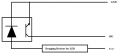
There are four possible leads from the control circuit this will connect to
Mains+ (12-18 volts DC)
Vcc+ (5.1 volts DC)
SIG (5.1 volts DC)
GND (common ground)
The control circuit is designed to trigger the particular event I want when SIG is shorted to ground (pulldown?), so I need to emulate this using the optical sensor,
Can anyone help me? I'm not opposed to spending a little money here!
Thanks!
Before I get a question asking why not just use one of the aforementioned sensors, it's because the source of the input will be a brass flywheel turning at potentially high speeds, and I don't have the tools nor mechanical know-how to mount a magnet to it and properly counterbalance it for smooth operation.
So, I would like to design a sensor circuit around the ON Semiconductor QRE1113, but need some help
There are four possible leads from the control circuit this will connect to
Mains+ (12-18 volts DC)
Vcc+ (5.1 volts DC)
SIG (5.1 volts DC)
GND (common ground)
The control circuit is designed to trigger the particular event I want when SIG is shorted to ground (pulldown?), so I need to emulate this using the optical sensor,
Can anyone help me? I'm not opposed to spending a little money here!
Thanks!