
Hi All,
First post here so be gentle, came here to try and narrow down an issue i have on a project in London. Its 9 floors of lift lobby lighting driven by 17-21 DALI drivers per floor and 6 emergency lighting supplies per floor for when the power goes out.
Overview
Each driver cabinet contains typically:
In an ideal scenario each lift lobby (illuminated with 4.8W/m LED tape above a stretch ceiling membrane) powered by 17no. DALI drivers runs at approximately 70% (dimmed via DALI signal) then when the power goes out in the building the 6no. emergency lighting drivers should detect the power outtage and switch over to battery packs for 3 hours. Almost all of the time this does happen, with the exception of a couple of battery packs which arent charging and therefore dont activate.
The real trouble arises when the power turns back on and lots of switching has to happen in the driver box.
Also worth noting, the driver box is quite large and is split in two, it has a 'main body' and a 'door', there are 9 DALI drivers in the main body and 8 in the door, and 3/4 emergency drivers in each side. The 240V supply coming in to the box has been split to so as not to cause a huge inrush at switch on, so the main body of the box goes on first, then 5 second delay then the door powers up.
When the power switches back on after an outtage the sequence goes something like this.
1)Emergency drivers switch off
2)Main body DALI drivers (LED panels) switch on with the exception of the emergency drivers and panels
3)Main body emergency drivers and panels then switch on
4)Relay kicks in
5)Door panel DALI drivers (LED panels) switch on with the exception of the emergency drivers and panels
6)Door emergency drivers and panels then switch on
7)Ideally all the LED panels are back on at this point
When all of that switching is done with there is a random assortment, sometimes 1, sometimes 3/4 LED panels which dont power back up again. Its not localised to only emergency lighting drivers or just the DALI drivers.
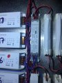
All the components in the boxes are EMC tested so there shouldnt be any intereference internally within drivers themselves, although thats obviously not the case. Ive attached a photo of a section of the driver and emergency wiring so you all can see crudely what it looks like.
Any help on why things arent all switching back on would be greatly appreciated, Im at a loss and also well out of my depth!! I dont know what to do!! HELP.
Footnote: I was advised by the emergency lighting driver manufacturer to install ferrite coils to the main input of the emergency drivers (3 turns of LandN around a coil), this had no effect and in some instances made the situation worse, with more panels failing than before!!
First post here so be gentle, came here to try and narrow down an issue i have on a project in London. Its 9 floors of lift lobby lighting driven by 17-21 DALI drivers per floor and 6 emergency lighting supplies per floor for when the power goes out.
Overview
- LD8CO300DK (Emergency DALI Lighting Driver)
- LTECH DALI-75-24-F1M1 (DALI Driver)
- LED array
- 22V approx, 70W at full power
- base circuit: 6 LEDs in series with IC to regulate current to 30mA
- multiple base circuits in parallel
Each driver cabinet contains typically:
- LTECH DALI-75-24-F1M1
- 17 pcs
- LD8CO300DK
- 6 pcs
In an ideal scenario each lift lobby (illuminated with 4.8W/m LED tape above a stretch ceiling membrane) powered by 17no. DALI drivers runs at approximately 70% (dimmed via DALI signal) then when the power goes out in the building the 6no. emergency lighting drivers should detect the power outtage and switch over to battery packs for 3 hours. Almost all of the time this does happen, with the exception of a couple of battery packs which arent charging and therefore dont activate.
The real trouble arises when the power turns back on and lots of switching has to happen in the driver box.
Also worth noting, the driver box is quite large and is split in two, it has a 'main body' and a 'door', there are 9 DALI drivers in the main body and 8 in the door, and 3/4 emergency drivers in each side. The 240V supply coming in to the box has been split to so as not to cause a huge inrush at switch on, so the main body of the box goes on first, then 5 second delay then the door powers up.
When the power switches back on after an outtage the sequence goes something like this.
1)Emergency drivers switch off
2)Main body DALI drivers (LED panels) switch on with the exception of the emergency drivers and panels
3)Main body emergency drivers and panels then switch on
4)Relay kicks in
5)Door panel DALI drivers (LED panels) switch on with the exception of the emergency drivers and panels
6)Door emergency drivers and panels then switch on
7)Ideally all the LED panels are back on at this point
When all of that switching is done with there is a random assortment, sometimes 1, sometimes 3/4 LED panels which dont power back up again. Its not localised to only emergency lighting drivers or just the DALI drivers.
All the components in the boxes are EMC tested so there shouldnt be any intereference internally within drivers themselves, although thats obviously not the case. Ive attached a photo of a section of the driver and emergency wiring so you all can see crudely what it looks like.
Any help on why things arent all switching back on would be greatly appreciated, Im at a loss and also well out of my depth!! I dont know what to do!! HELP.
Footnote: I was advised by the emergency lighting driver manufacturer to install ferrite coils to the main input of the emergency drivers (3 turns of LandN around a coil), this had no effect and in some instances made the situation worse, with more panels failing than before!!
Attachments
-
 281 KB Views: 12
Last edited:


