Facebook
 Google
 GitHub
 Linkedin
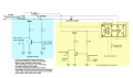
I have a simple DC power control circuit that I want triggered by reed relays. It is for model railroad use. One set of reed switches detects the passing of the train . The first switch turns the power on to a trolley car so as the train passes the trolley car is moving. The second reed switch turns off the power as the train passses that point. Then the trolley stops and waits for the next train.
Reed switches 3 and 4 are on the trolley track and when the trolley triggers either, the voltage output is reversed causing the trolley to move in the opposite direction.
The trolley may draw up to 900mA
This is all based on the first diagram on this page https://www.electronics-lab.com/project/simple-soft-latch-switch-using-push-button/
I do not want to complicate this more, as I figure simple is best. I have seen some similar circuits with 2 to 3 tiems the components
I added electrolytic capacitors and diode because load is inductive, and changes polarity and wanted to protect against reverse voltage, and noisy power wupplies.
Addded S5 to have the option of "remembering" or "resetting (forgetting)" the direction that the train last travelled and resuming in same direction.
Attachments
-
 73.1 KB Views: 15