Need Help with circuit board

Thread Starter

Dan the rookie

Joined Jun 17, 2020
10
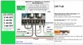
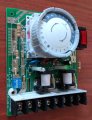
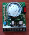
Hi! This is the circuit board from an outdoor timer for switching a pump on and off. It can handle 120-240-277V depending on the connections chosen at the bottom. When I wired it up with 240V, I forgot the order of operations and accidentally blew it out when I applied load. I used my multimeter to determine that the resistors indicated by the sloppy yellow arrows are blown.
Does anyone know where I can find replacement resistors for these? I think they are 91ohm, 5% (white, brown, brown, gold), and 1.2kohm, 5% (brown, brown, red, gold). I don't know how many Watts though.
Any help at all is much appreciated.

Thank you all!

timer circuit.jpg
 

ThePanMan

Joined Mar 13, 2020
773
Resistance value matters to proper functioning of the circuit. Size (in wattage) is only as important as it is to have big enough resistors. If you put a quarter watt resistor when you should have put a half watt resistor you'll burn it up real quick. Whereas if you put a 1 watt resistor, it will handle the load. So don't go smaller in size (wattage) and stick as close as possible to the original ohms value.

Those resistors don't look blown to me. Are you sure they're open? Could it be a bad solder joint? burned trace somewhere? Fully diagnose the problem before you start fixing things.
 

Thread Starter

Dan the rookie

Joined Jun 17, 2020
10
Resistance value matters to proper functioning of the circuit. Size (in wattage) is only as important as it is to have big enough resistors. If you put a quarter watt resistor when you should have put a half watt resistor you'll burn it up real quick. Whereas if you put a 1 watt resistor, it will handle the load. So don't go smaller in size (wattage) and stick as close as possible to the original ohms value.

Those resistors don't look blown to me. Are you sure they're open? Could it be a bad solder joint? burned trace somewhere? Fully diagnose the problem before you start fixing things.
Thank you for your reply! :)

When I test the resistance across these two resistors, it's a flat zero. (It buries the needle on my analog multimeter)
I blew the circuit board by jumping way too much power, and I saw a small flash inside the timer,and it hasn't worked since.

I figured to not go light on the power rating, but I don't know how to tell what the original rating is.
 

LesJones

Joined Jan 8, 2017
4,174
It is very unusual for resistors to fail short circuit. Did you unsolder one end the resistor before testing it's value ? If you did not the short may be elsewhere on the board.

Les.
 

Dodgydave

Joined Jun 22, 2012
11,285
Just looking at the PCB, the set of Dip Switches are probably to short out some of the resistors for lower mains voltage, ideally remove one end of each resistor and recheck.
 

MisterBill2

Joined Jan 23, 2018
18,176
While something must have failed those resistors do not give the appearance of being damaged. so something else has failed. My guess is that those resistors are indeed bypassed by the dip switch. and if they were bypassed when they should not have been, then some other part failed with a flash when the excess voltage was applied.
Probably it is a more complex part hidden by that large dial.
 

Tonyr1084

Joined Sep 24, 2015
7,853
I've not often seen a glass fuse flash when it blows, but it might be as simple as a blown fuse. Take some more pictures from different angles and post them. OR if you can identify a fuse - check that.

A resistor should read XΩ or open. Never 0Ω. Well, to qualify that, there are some surface mount resistors with a value of zero ohms, but mainly, they're just jumpers. Those resistors are not jumpers. They should read some resistance. But like others have already said, they may be jumped out of the circuit.

To address your comment about size (wattage), "Size" is the key. R3 may be a half watt resistor. Given that it's up off the board, the engineers expect it to run warm (or even hot). The spacing off the board promotes air flow around it to strip away excess heat. Also, the longer leads dissipate heat. Since scale is really difficult to say, I wouldn't just assume R3 is a half watt resistor. It may be. OR it could be a 1 watt resistor. Still, I believe none of us think you need to replace those two resistors.

[edit] R8 (for example) appears to be a quarter watt. R4 MIGHT be an eighth watt (1/8) resistor. Again, size is hard to determine via the picture. [end edit]
 

Thread Starter

Dan the rookie

Joined Jun 17, 2020
10
It is very unusual for resistors to fail short circuit. Did you unsolder one end the resistor before testing it's value ? If you did not the short may be elsewhere on the board.

Les.
@ Les: No, I had not thought to do that. I tested the resistors on the PCB by touching the wire leads with my multimeter probes. Maybe that's not the right way in this case? Maybe I'll try removing the dial to give everyone a better look. See if there's a fuse back there.

One other thing. I don't think I shorted the circuit. I overloaded it by trying to wire 240V source into a 120V style switch, so when I threw the switch it put a lot more voltage into the circuit. Maybe... Maybe not.

p.s @Dodgydave : the resistors turned out to be W,Br,Br,Go and Br,Br,O,Go on a closer inspection. So I now think they are 910ohm and 11kohm thanks to your advice. Thank you.
 

Tonyr1084

Joined Sep 24, 2015
7,853
Maybe that's not the right way in this case?
No. The reason why that's almost never the case is because when you have two resistors in parallel, you will read both of them AND you will read half to way below the rated value. It has to do with Ohm's law. If you know it then there's no need to explain it. In short - when testing a resistor in circuit - you're not likely to get a correct reading. So yes, the right thing to do would be to remove one of the leads from the circuit and test it. I'm confident you'll find those two resistors are good. They COULD be cracked, in which case you'd have an open; but never a short. At least I've never seen a resistor go short.
 

BobTPH

Joined Jun 5, 2013
8,813
I overloaded it by trying to wire 240V source into a 120V style switch, so when I threw the switch it put a lot more voltage into the circuit.
I don’t think so. A switch rated for 120V and used at 240V would probably work initially but wear out quickly. It cannot put extra voltage on the circuit.
Bob
 

BobaMosfet

Joined Jul 1, 2009
2,110
I would make sure your analog meter is good- could be you've blown it, or its battery is dead. Those resistors look OK (that is not how a resistor of that type looks when it fails, - they burn, blister, blow chunks out.
 

LesJones

Joined Jan 8, 2017
4,174
Looking at the timer part it looks like a mechanical timer which is just an electric motor driving the dial through reduction gearing, I don't think there will be any components underneath it on the board. I agree with Dave's post #7. If you set all the DIP switches to the open position you may find you get the correct or at least a higher value than zero ohms for the resistors you think are faulty. If you post a picture of the other side of the board it might help. Is this a new timer or one that has been in service for some time ? I noticed when looking more closely at the picture the the NO side of the contacts on the right hand relay look like they are burned. Did you change the wiring to the output switching connections on the timer or just the connections that power the timer ?

Les.
 

MisterBill2

Joined Jan 23, 2018
18,176
Back in post #8 I suggested that the dip switch is bypassing the resistors. AND it is possible to grossly over-power a small clock motor and burn the winding open. Next, consider that this board has at least two relays switching something., and a third device along what we see ast the right side of the board. So clearly it is more than just a mechanical timer. Of course it may also be that the damage is on the underside of the board, or even at the mechanical switch operated by the timer.
 

Thread Starter

Dan the rookie

Joined Jun 17, 2020
10
This timer was only used for about 1 minute. I first wired in the load and grounded it, and then attached those to a two pole switch. When I closed the fuse at the fusebox, the power started driving the pump (because it was using 120V), and I let that go for about a minute, and then I threw the switch which added the second load line to the circuit. That when the action happened. There was a small flash from the timer box and the traditional 'bzzzzt' noise, and that blew the fuse. It was only a half-second. When I took the timer apart, this is what it looked like.
I'll try to remember to send a second photo tonight. There are jumper wires that connected the screws at the bottom, but I'm highly confident that I did those right for 240V. The DIPs are in the correct positions for 240V.
I really appreciate everyone's input, as I clearly have little experience in circuit boards and electronics.
 

LesJones

Joined Jan 8, 2017
4,174
From your description I don't think the blowing of fuses is related to to configuring the timer for 120 volts and supplying it with240 volts. I am assuming you are in the US or Canada from the fact you 120 and 240 volts available. Can you post a schematic of EXACTLY how you wired the supply to the timer and the wiring via the contacts on the timer to the loads (Including the ground connections.) When you say "threw the switch " where is this switch in the circuit ? Can you also confirm if the black and orange thing to the right of the timer dial is an illuminated switch or an inductor. (The orange part looks like it may be the windings on an inductor.) Can you also post the documentation supplied with the timer ?

Les.
 

Thread Starter

Dan the rookie

Joined Jun 17, 2020
10
The black and orage thing is the switch to choose "on/off/timer". That's written on the body. It's from a GE model 15135 Mechanical Time Switch. I used the directions on the inside of the box's door to set the DIPs for 240V. They did not include a wiring diagram or other instructions, so I got one from here: <http://waterheatertimer.org/How-to-wire-GE-15135-timer.html>
On the back of the PCB, the area where the 'NC' lead is soldered in seems slightly lifted, but there is no crack in the solder joint. Also, I did not connect a wire to the 'NC' lead, because that's not in the diagram.
Thanks again to all for your interest and assistance.
Dan
 

Attachments

Top