Facebook
 Google
 GitHub
 Linkedin
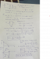
The below is the circuit


Few questions keep coming up is when i consider ideal diode or when it is not mentioned and if anode and cathode are at the same voltages as in the case above shall i consider it is forward biased or reverse biased?
Is there any step-by-step procedure to analyze any circuit or randomly we have to think?
In the above circuit the Anode is at ground voltage and the cathode also at ground voltage so i assume the diode as reverse biased, is it correct?
In that case one side of the capacitor is open circuited and capacitor voltage shall not increase, or shall i consider very high reverse diode resistance and apply Laplace transform? I am really failing to analyze the above circuit.
For inductor is
V = L*di/dt -> I = V*t/L -> (1)


")