 Facebook
 Google
 GitHub
 Linkedin
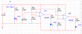
My group at school had to design a 3 controller system with time delay, we have 3 LEDs the red LED turns on immediately, Green LED 2 turns on 2 seconds after the red LED turns on, and the yellow LED 3 turns on 3 seconds after the Red LED, the multisim diagram is attached and we confirmed on the breadboard it works, we have two resistors in series and it feeds the negative input of the LM324N, my question is how does voltage divider rule trigger time delay into the LM324N?
Attachments
-
 18 KB Views: 15


