Need help to light up 8 LEDs with different color

Thread Starter

jenovauh

Joined Jul 4, 2013
246
Hi Benard I have done the instruction you mentioned.

1.Lift one end of D2 & adjust BBR1 to 10 V, are LEDs on? Yes LEDs are on
2.Lift D1 & adjust BR1 to 9.5 V, are LEDs on? No LEDs turn off
3.Use RSP, 10k pot as an adjustable V supply. Lift R27-2 & connect it to RSP-2. Adjust RSP-2 to 11.5V, or to battery spec. for minimum discharge V. D-7 should be low. What does RSP mean? Anyway I assume is to use additional VR and adjust pin 2 to 11.5V then connect to R27 pin 2.
4.
Lower R28-2 slowly until D-7 goes high. Battery is now disconnected from BR1 & Q4 & will remain disconnected until battery is charged to about 12.6V. I tuned R28 but it does not affect D7 Voltage.

So now I am pretty much stuck here and could not proceed further. I check on the B1(charging battery), the voltage is draining slow instead of charging.
 

tracecom

Joined Apr 16, 2010
3,944
My buck and boost-buck regulators have not arrived; perhaps they will be here tomorrow. Until they arrive, I cannot test any further. I tried to substitute, but no go.

Post a photo of your assembly, and I will try to spot any errors in connections.
 

Thread Starter

jenovauh

Joined Jul 4, 2013
246
My buck and boost-buck regulators have not arrived; perhaps they will be here tomorrow. Until they arrive, I cannot test any further. I tried to substitute, but no go.

Post a photo of your assembly, and I will try to spot any errors in connections.
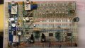
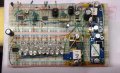
Thanks for helping tracecom. I have taken the photo in panorama view. Hope you can see them clearly.
 

Attachments

tracecom

Joined Apr 16, 2010
3,944
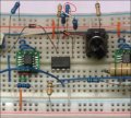
I think I have successfully completed Bernard's last procedure. During that process, I discovered that I had R29 pin 1 connected to ground. I corrected it to connect R29 pin 1 to U3 pin 2. You might have copied my layout and made the same mistake I did. Better check it. The schematic is correct, but my breadboard was wrong in the photo I posted.

ETA: If the resistor I have circled on the attached snip is R29, then it looks like you may have duplicated my mistake. R29 should not go to ground, but should be connected to U3, pin 2.
 

Attachments

Last edited:

Thread Starter

jenovauh

Joined Jul 4, 2013
246
Yes on the photo looks like I had follow and made that mistake lol. After work I will go home and check it and try out again.
 

Thread Starter

jenovauh

Joined Jul 4, 2013
246
Hi tracecom, can I know you did these procedure with one or two 12V battery? First instruction was to substitute B1 pin 1(+) to BBR1 TB2 pin 1(+). That mean I need 2 battery right? one battery act as solar panel and the other is charging battery.

And also on my post 341, am I getting the correct result?
Item number 2.Lift D1 & adjust BR1 to 9.5 V, are LEDs on? No LEDs turn off, my output of BR1 actually have no voltage at all.

I will figure out while you guys are here to enlighten me.
 
Last edited:

tracecom

Joined Apr 16, 2010
3,944
@jenovuah

I don't have any solar panels or batteries at all, so I am using power supplies. And I don't have any buck or boost-buck converters, so I have built a set of three external voltage dividers to simulate the variable voltage outputs. Also, I only have one LED that simulates your array of LEDs.

All this is because I am only trying to duplicate the comparator operations and don't really need full power. But I think Bernard meant for you to use the output from your battery to simulate the solar panel; he said to connect B1, which is the reference to the battery on the schematic.

After you correct the connection of R29, run your test again. I think it will work as Bernard said. I will be back here after I go for breakfast. Good luck.
 

Thread Starter

jenovauh

Joined Jul 4, 2013
246
Okay enjoy your breakfast.
Yes I did and it is not working, I think it is because BR1 output does not have any voltage, I measured the input to BR1 which is only 0.5V and maybe that's why it does not have output.

Hi Benard when you are online are you able to advise on my post 341, are the result I got is correct or not. Thank you.
 

tracecom

Joined Apr 16, 2010
3,944
The input to BR1 is controlled by U2. When pin 1 of U2 is low, Q3 is turned on and powers BR1. Remember that you can adjust R20 to control U2 pin 1.
 

Thread Starter

jenovauh

Joined Jul 4, 2013
246
Okay got it now, my R20 was adjusted to allow U2 pin 1 at 11.5V.

So right now the issue is D7, adjusting R28-2 does not affect D7 voltage. I am thinking the D7 which Bernard had mentioned is it correct? As it is at the LED circuit and not the charging circuit.
 

tracecom

Joined Apr 16, 2010
3,944
Okay got it now, my R20 was adjusted to allow U2 pin 1 at 11.5V.

So right now the issue is D7, adjusting R28-2 does not affect D7 voltage. I am thinking the D7 which Bernard had mentioned is it correct? As it is at the LED circuit and not the charging circuit.
No, I think you misunderstand. When Bernard says D7, he means U4, pin 7, i.e., comparator D, pin 7.
 

Thread Starter

jenovauh

Joined Jul 4, 2013
246
No, I think you misunderstand. When Bernard says D7, he means U4, pin 7, i.e., comparator D, pin 7.
Yes totally misunderstood as he mentioned before he will use the label in the circuit. :)

Okay anyway I had adjusted R28-2 slowly and it does not increase voltage slowly but it jump straight to 11.65V on U4 pin 7. Even if I adjust R28 all the way to increase voltage it doesn't, either it drop to +0.1V or +11.65V.

After all these step is done what else do I miss or need to do? Actually I still don't really understand all these testing is for what? All the 2 extra VR in the circuit suppose to be fixed in the circuit with fixed resistor and all the existing 3 VR in the circuit as well?

Also I don't understand this phase here "When D-7 goes high, low battery, R20 is removed by rev. biased D4, changing D-5 back to 2.5 V ref. The V divider R28 & R 27 is about 5:1, so 5 X .2V differance represents a 1 V change in battery V, 11.5 + 1 [ 1.1 with R29 @ 22k ]= 12.5 [ 12.6 ] for battery reconnect"
Am I suppose to change some components here?
 

Thread Starter

jenovauh

Joined Jul 4, 2013
246
After the last steps was completed, I had my DMM on the battery to check if the battery voltage have increase but it doesn't seem to be charging it.
 

Bernard

Joined Aug 7, 2008
5,784
Just an explanation of the workings, no part changing. Also I will referr to parts as labled by tracecom, so no more D= diode or D = U4.2
Once a pot has been set to proper value, it should not be changed unless instructed to. Going to figure answers to previous questions.
Remember that charging circuit has not been activated yet, need to have everything operating properly first before adding charging.
 
Last edited:

Thread Starter

jenovauh

Joined Jul 4, 2013
246
Just an explanation of the workings, no part changing. Also I will referr to parts as labled by tracecom, so no more D= diode or D = U4.2
Once a pot has been set to proper value, it should not be changed unless instructed to. Going to figure answers to previous questions.
Hi Bernard, :) welcome back. By the way all the test is done. What should I set exactly to make it work normally. Like day using solar panel to light up LEDs circuit and charge the battery. Cloudy day battery will take over and night time totally cut off power.
 

Bernard

Joined Aug 7, 2008
5,784
BR1 V adjustment:
Lift D1-1, add temporary jumper from U4-5 to ground, adjust R28-2 to max V at U4-6, around 4V. Is Q3-4 low? If yes, then is there V on TB5-1, input? If yes, adjust BR1 to 9.5V. Are LEDs on? If yes, go to Low battery adjustment.

Low battery adjustment:
Lift R27-2 and connect to an adjustable V like RSP-2, 10k pot used before as SP substitute. Set V to 11.5V. Reconnect R27, remove U4-5 jumper. Is U4-7 low? If yes, go to next step, No, re touch U4-5 to ground to reset U4.

Charge control:
Is there about 10.5V at R22-2? Yes, then adjust R23-2 to R22 V -.2 V , about 10.3V. Best if a seperate power supply is used for SP, nice if it is adjustable and can deliver .5A [ 50 ma for tracecoms one LED ].
Now, how we think it is suposed to work.
Not knowing how much excess power is available for battery charging, we just dump all SP power into the battery, if BBR1 holds V at 10.5V, battery charges at max available current; most likely BBR1's output will fall below 10.5V, at 10.3V, U4-1 goes high & after a short delay [ R25, C6 ] Q4 turns off; unloaded V climbs turning Q4 back on with short delay. The battery is then charged with pulses of current. We do not want the D1-1 V, to fall below 9.5V or we start running the LED's on battery power. May need to shorten R X C time constant,like R24 to 10k , if not enough C6 to .1.
 

Thread Starter

jenovauh

Joined Jul 4, 2013
246
Charge control:
Is there about 10.5V at R22-2? Yes, then adjust R23-2 to R22 V -.2 V , about 10.3V.
No mine is 10.03V and adjusting R23 all the way will only reach 10.1V. Is that okay?

Best if a seperate power supply is used for SP, nice if it is adjustable and can deliver .5A [ 50 ma for tracecoms one LED ].
I am using a separate battery to substitute the SP and I don't have an adjustable power supply. Will consider buying one or tracecom can teach me how to make his. :)
 
Last edited:

Thread Starter

jenovauh

Joined Jul 4, 2013
246
No mine is 10.03V and adjusting R23 all the way will only reach 10.1V. Is that okay?
Okay I figure that should adjust BBR1 itself to change the voltage to 10.3V. And also later adjust R23-2 will only be able to drop the voltage to 10.26V.

BR1 V adjustment:
Lift D1-1, add temporary jumper from U4-5 to ground
After all the adjustments, do I need to place D1-1 back to where it should be? And also the temporary jumper from U4-5 to ground, need to be remove? Oh one more the RSP 10K pot?
 
Last edited:

Bernard

Joined Aug 7, 2008
5,784
Put D1-1 back in place & measure V at D1-1 with LEDs on & report finding. Reset BBR1 to 10V and leave it there. Measure V at D1-2 & report finding. Connect R22-2 to 10k pot & set wiper to D1-2 V minus .2V. Adjust R23-2 to where U4-1 switches , work potU4-1 will jump up & down; stop when just a little movement causes a switch back & forthReconnest R22-2.

Remove U4-5 jumper. Except for unknowns should be ready for sunshine & shadows.
 
Top