Thanks for the advice Bernard, I will do that later when I am home and update the findings again. Currently I am sure that the circuit did not charge the battery or power by battery when cloudy. I simulate it by partially cover the solar panel.
I finished wiring my regulators yesterday, and, as usual, connecting the actual components per the schematic helped to better understand the circuit. I am actually using a buck regulator to simulate the solar panels, so I will be able to dial in any voltage out that I need for testing. A photo is attached. The layout is intentionally spread out to facilitate test connections. I would tighten it up in a finished project.
I had previously wondered if all the grounds from the regulators were continuous through the regulators, and now know that they are. So, I will be able to eliminate a couple of ground lines from the schematic.
Also, I bought a battery last night, and that is the last piece I need to construct a complete system, which I should be able to do today. Then, I can begin testing in earnest.
That's great Tracecom and thank you so much for replicating this project and test out together with me. . I just found out that ebay is selling Constant current and constant voltage DC step up and down buck. I had purchased one today. So I am able to control the current that flow into the circuit from the battery to simulate the result.
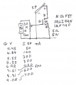
jenovauh, I think thst you have a power N ch FET & with a heat sink will do nicely for an electronic load for testing SP's. I do not have a 5Ω 5W resistor, so used a 5.6Ω, 1/2 W in a glass of water. Just about any value pot will do, & so with battery, 9V to 12V. G v vs SP I just for refferance.
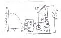
He wants you to measure the output from one of your solar panels by setting up the circuit in the diagram and then measuring the voltage at different currents. In order to adjust the circuit, he wants you to use a multi-turn pot (10 turns or more.)
In post # 378 you asked for a simple load to test SP's. This one is pretty simple. I used a 10 turn pot, but any pot would work, say 5K to 100k. Just about any SP greater than 3W should work with some pot adjustments.
jenovauh, I think thst you have a power N ch FET & with a heat sink will do nicely for an electronic load for testing SP's. I do not have a 5Ω 5W resistor, so used a 5.6Ω, 1/2 W in a glass of water. Just about any value pot will do, & so with battery, 9V to 12V. G v vs SP I just for refferance.
I calculated I can use 1 X 10 ohms 1W and 4 X 47 ohms 1W to form 5.4 ohms 5W. I hope that's correct. Anyway I can only measure the solar panel on this coming weekend.
Just a quick note for jenovauh, when measuring LED current; be sure that LED's are static, not flashing. You can ground Q1-3 & measure V across some of the 100 Ω Rs, R5 -R9, with VCC [ 555-8 ] of 10V.
Hi Bernard, I had set the VCC of 555 pin 8 to 10V and did the measurement across from R5 pin 1 to Q1 pin 3 @ 49.5-50.5mA so it is about 16mA per LED in the string of 3 LEDs
Hi tracecom, how is your testing result on the whole circuit? Anything else I can do to check other than to wait for weekend to confirm solar panel?
I have taken a detour to try to better understand comparators in general and the LM393 in particular. That is finished and I will return to the testing tomorrow. (Today is Thanksgiving Day, and my wife and I are going to eat with my brother and sister and their families.)
jenovauh, your readings are a bit confusing, we were looking for V readings across R5, R6 R7, & R9, with Q1-3 grounded. For a 50mA reading, sounds like LED1,2,& 3 were shorted by A-meter,& Q1 fell out of saturation, or VCC fell out of regulation??
jenovauh, your readings are a bit confusing, we were looking for V readings across R5, R6 R7, & R9, with Q1-3 grounded. For a 50mA reading, sounds like LED1,2,& 3 were shorted by A-meter,& Q1 fell out of saturation, or VCC fell out of regulation??
Hi Bernard I did not connect any LEDs in that strings. Nothing is shorted to test or get that measurement. I basically just remove the 3 LEDs then the existing Q1 pin1 is to ground, pin2 is connected to 1k resistor, pin3 I connect to negative pin of DMM and positive pin of DMM to R5 pin1
I have taken a detour to try to better understand comparators in general and the LM393 in particular. That is finished and I will return to the testing tomorrow. (Today is Thanksgiving Day, and my wife and I are going to eat with my brother and sister and their families.)
Anyway just an update, wasn't able to measure the solar panel as it have been raining for days.
Hi Bernard, after reading on your post again. I realize you are asking me to measure the voltage across. Sorry that I made a mistake as my mind was expecting to measure the current flow. The voltage across are about 9.4 voltage from R5 to R9.
The weather has been good here for a few days (considering that it is December and should be cold and rainy,) so I have been outside a lot. I have been sidetracked, but I have not forgotten your project. I will get back on it this week.
Let us try again to measure one string of LED current by measuring V across R5, neg V meter lead to R5-1, + lead to R5-2. But first we need to know V U1-8. [ should be 10V ]. & to prevent possible disturbance , disable charging by connecting a temp. jumper from R25-2 to R24-2, which will make Q4 gate high, keeping it off; connect a temp. jumper from Q1-3, collector, to Q1-1, shorting Q1 so that there will be a steady current flow thru the first group of LED's. I suspect that R5 & others are too high in value, so for 20 mA V reading across R5 should be 2V. Measure several other Rs, inc. R9.
Sure I will do that Bernard. Do you think I should just disconnect the LED circuit from charging circuit. Then power the LED circuit direct from a 12V battery thru a buck and set it to 10.5v?
I have finally gotten all the parts together. I am using a separate buck regulator to simulate the solar panels, so I can adjust it to simulate any output from 15V to 0V. I have successfully completed the day/night procedure in post 297. Everything is working as expected to that point.
I have completed the procedure in post 326 as far as "Lower R28-2 slowly until D-7 goes high." Everything went as expected.

 Facebook
 Google
 GitHub
 Linkedin



 . I just found out that ebay is selling Constant current and constant voltage DC step up and down buck. I had purchased one today. So I am able to control the current that flow into the circuit from the battery to simulate the result.