Need help to light up 8 LEDs with different color

Thread Starter

jenovauh

Joined Jul 4, 2013
246
3. Create a variable voltage source by using a pot of 1k or 5k or 10k; it doesn't matter. Connect one side of the pot to +12 and the other side of the pot to ground. Then the wiper (he calls it the tap) will have a voltage on it somewhere between 0 and 12V. Adjust it until the voltage on the wiper is 4 volts.
Hi tracecom thank for the explanation, I just dont understand when I connect the 1k pot to the +12V and ground. How to get the 4 voltage, I mean where do I measure to know that it is 4V? Also correct me if I am wrong, the pot you guys are referring to have 3 pin right?
 

tracecom

Joined Apr 16, 2010
3,944
A pot has three terminals: two end terminals and a center terminal called a wiper or a tap. If a pot is a 10k pot, there will be 10000 ohms of resistance between the two end terminals. The resistance between the wiper and one end terminal plus the resistance between the wiper and the other end terminal will total 10000 ohms. When you turn the pot, you are moving the wiper toward one end terminal and away from the other end terminal. So, the resistance between the wiper and an end terminal will change as you turn the pot.

To set up a voltage divider, you connect one end terminal to +V and the other end terminal to ground. Then you measure the voltage between the wiper and ground. The voltage will be somewhere between +V and ground. As you turn the pot, the voltage will change; turn the pot one way and the voltage will increase, turn it the other way and the voltage will decrease.

You can verify all the above with your DMM.

If your pot smoked, it is because you connected one end of the pot to ground, but instead of connecting the other end of the pot to +V, you connected the wiper to +V. Then, when you turned the pot, the resistance went to 0 ohms and the current was too high, and the pot overheated. it is ruined and should be thrown away.

Try again to set up a voltage divider with another pot. Be sure to connect the ends to +V and ground and leave the wiper unconnected.

I must go to bed by 11:00 p.m., so respond before then.

Good luck.
 

Thread Starter

jenovauh

Joined Jul 4, 2013
246
3. Create a variable voltage source by using a pot of 1k or 5k or 10k; it doesn't matter. Connect one side of the pot to +12 and the other side of the pot to ground. Then the wiper (he calls it the tap) will have a voltage on it somewhere between 0 and 12V. Adjust it until the voltage on the wiper is 4 volts.
4. Connect R19 pin 2 to the pot wiper with 4V on it.
I fully understand this and got to adjust to 4V and connect wiper to R19 pin 2.

5. Connect you volt meter to U1, pin 1 and get ready to measure the voltage.
I think you meant by connect to U2 - pin 1

6. Adjust R20 until the voltage reads very close to 12V.
I connect U2 - pin 1 to R20 pin 2, are able to adjust from 8.19V to 11.93V.

7. If the voltage is very low, disconnect the power, and reconnect the power.
Which voltage is very low? I tried disconnect the power(solar) and reconnect the power(solar). The voltage measure from R20 pin 2 to U2 pin 1 down by 0.2V.

8. Now adjust R20 slowly until you see the voltage drop from 12V to almost 1V.
Now, the sensitivity of U2 is adjusted.
No Matter how I adjust R20. I wouldnt get any lowest than 8.19V.

Maybe I am not doing correct or measure wrongly. :(
 
Last edited:

tracecom

Joined Apr 16, 2010
3,944
I was mistaken when I said to connect to U1; I meant U2.

So, you have made some progress. That's good.

It may be that U4 is interfering. To eliminate that possibility, disconnect D5 from D6, and try again to adjust R20.

Although I am able to make U2 switch from 12V to less than 1V by adjusting R20, I am still having some trouble, which I don't understand. It may be that the exact sequence in which the adjustments are made is crucial. I will try to test some more this morning, and maybe gain some understanding.

If I make progress, I will post. But after this morning, I will be busy with another matter and won't be able to work on this again until the middle of the coming week.
 

tracecom

Joined Apr 16, 2010
3,944
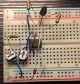
I have rebuilt my breadboard to make it easier to follow. Of course, this is just the U2 comparator section; the rest will be added as required.


The pot labeled 10k is the voltage divider that is adjusted to +4V. Notice that the pots are laid out with pin 1 to the left, pin 2 in the center, and pin 3 to the right. It is important that yours be laid out the same way.

Red wires are connected to +12V; black wires are connected to ground.

To adjust the switchover point of U2:
1. Disconnect or turn off +12V.
2. Disconnect R19 from pin 1 of R20.
3. Connect DMM to pin 2 of 10k pot.
4. Reconnect or turn on +12V.
5. Adjust 10k pot so that there is +4V on pin 2.
6. Disconnect or turn off +12V.
7. Reconnect R19 to pin 1 of R20.
8. Turn R20 fully clockwise.
9. Connect DMM to pin 1 of U2.
10. Reconnect or turn on +12V.
11. Voltage at pin 1 of U2 should be +12V.
12. Slowly turn R20 counter-clockwise until the voltage falls to less than +.1V. Note that the voltage does decrease gradually; it stays at +12V as the pot is rotated and then falls suddenly to less than +.1V. Also note that after the voltage falls, turning R20 clockwise will not raise the voltage at all. In order to reset the voltage to +12V, go to step 6 and follow the steps again.

The switchover point is now adjusted to +4V from the solar panels.

Note that my breadboard is completely isolated from the rest of the circuitry. Due to the complexity of the circuit, it may be necessary for you to duplicate my setup and then perform the adjustment. If you follow my example, and cannot duplicate my results, there are two possibilities: (1) you have wiring error, and/or (2) you have damaged U2 and/or U3, which must be replaced.

I'll leave it up to you as to whether you want to rebuild your breadboard to duplicate mine, but it might turn out to be the easiest in the long run. You could leave U1 and its supporting circuitry and the LEDs as they are, since they are apparently working.

Good luck.

@Bernard, I notice that sometimes when following the procedure defined above, the output from pin 1 drops from +12V to +4.7V and then drops on to .07V as I turn the pot further.
 

Attachments

Last edited:

Thread Starter

jenovauh

Joined Jul 4, 2013
246
Sure tracecom, I will try that later after work when I reach home. By the way I notice that R20 measure 0 ohm from pin 1 to pin 2 and over limit from pin 2 to pin 3 when the circuit is power up.
 

Bernard

Joined Aug 7, 2008
5,784
To make it easier to watch, I inserted a red led between A-1 & R15, or parallel R15 with 3.3k & LED. I'll call 10k pot tap RSP, variable V, representing SP output & is connected to R19-2 for testing. Turn R20 up, RSP up, highest V. Apply power. LED on. Monitor RSP V, as V is lowered , at about 2.5 V LED goes off[ sun down ], increase RSP & note V, this is the minimum setting that will allow SP output to turn on Q3. Lower R20 a bit & re test, going lower than 2.5 & back up, note new value, lower R20 again until RSP is at 4V, sun up.
jenovauh, it would be helpfull if when giving voltages if the point measured were identified by part & pin number. tracecom did such a great job of identifing every thing, even #s on ends of resistors.
 
Last edited:

Thread Starter

jenovauh

Joined Jul 4, 2013
246
Post 293. What does U3-2 now measure, hopefully almost 2.5V?
I could not find what you mentioned here, think you had quote the wrong post number.

Jenovauh said:
Okay I have finished assembling and it is 3:35AM now. No sunlight to test yet so I use another 12V battery to act as solar panel and also connected charging battery.

This time the LED circuit light up, the charging circuit do not have any hot components. I check the charging battery but do not think it is being charged as the voltage remain the same after 5 minutes. If I unplug the battery acting as solar panel, the LED circuit will lights off. So maybe something is not right?

Anyway I measured both LM393, U2 have 12.33V and U3 have 12.3V. Pretty much the same and also LM336 is 9.21V.

Also there are 3 VR resistor, do I need to set any specify value on them. Actually what does they affect in the circuit?
If you are referring to this 293 post. The voltage is measured for pin 4 and pin 8 of LM393 which was asked by tracecom to test. Guess you did not read that post to understand.
 
Last edited:

tracecom

Joined Apr 16, 2010
3,944
Sure tracecom, I will try that later after work when I reach home. By the way I notice that R20 measure 0 ohm from pin 1 to pin 2 and over limit from pin 2 to pin 3 when the circuit is power up.
Remember the way a pot works. If you measure resistance from one end (say pin 1) to the wiper (pin 2) and then measure resistance from the other end (pin 3) to the wiper, the total of those two resistances will be the total resistance of the pot. As you move the wiper by turning the pot, the resistance on one side will go down and the resistance on the other side will go up, but the total will stay the same. To accurately measure resistance on a pot (or on a resistor) the pot should be disconnected from the circuit, and should not be under power.

However, what we are most interested in is the voltage out of pin 2 when the circuit is under power. We measure that voltage by connecting the DMM red lead to pin 2 and the black lead to ground with the DMM set to volts DC. We make that measurement with the pot in the circuit and with the circuit under power.

I have added U4 and associated components to my breadboard, and will label everything and post it after you get U2 working.

Oh, one other thing. Bernard asked about measuring U3. You can do that by setting the DMM to volts DC and connecting the red lead to U3 pin 2 and the black lead to ground. It must read very close to 2.5 VDC; if not it is probably shot.

By the way, you asked me one time how is the best way to learn electronics. The answer is to do just what you are doing: build something and make it work. But it can be frustrating, at times. :)
 
Last edited:

Thread Starter

jenovauh

Joined Jul 4, 2013
246
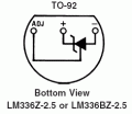
Hi tracecom, I replicated your setup, but U2 pin 1 still does not lower the voltage while slowly turn R20 counter-clockwise. I realize the LM336Z on your setup is different from mine. Is that an error ? I try to follow your facing but my on LM336Z got super hot after awhile lol. Did you insert all 3 pin? Cause I cant see your pin connection. LM336 suppose to be hot or not?
 

Attachments

Last edited:

Thread Starter

jenovauh

Joined Jul 4, 2013
246
Ok I connected the positive pin of U3 to pin 5 of U2, negative pin of U3 to ground and it works. When turning R20 slowing, nothing happen but suddenly it just drop to like no voltage. Is that correct and what I need to take note from here?
 

tracecom

Joined Apr 16, 2010
3,944
Ok I connected the positive pin of U3 to pin 5 of U2, negative pin of U3 to ground and it works. When turning R20 slowing, nothing happen but suddenly it just drop to like no voltage. Is that correct and what I need to take note from here?
Great news. Sounds like it is working fine, now. Pin 1 on U3 should not be connected to anything; I even cut pin 1 off my U3 so it would not be in the way, but that is not necessary.

So, the next step is to add on U4. I will try to take a photo of my breadboard and get it labeled.

Today, maybe Bernard will be able to give us instructions for setting U4.

P.S. Your breadboard looks good, and it's a good photo.
 
Last edited:

tracecom

Joined Apr 16, 2010
3,944
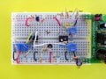
Here is my breadboard with U4 added. Note that I used a 220k for R31, a 22k for R29, and a BS250 for Q3. You will have to place Q3 differently than I did because of your breakout board pins.

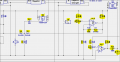
Also attached is a snip of the schematic with the added components highlighted.
 

Attachments

Thread Starter

jenovauh

Joined Jul 4, 2013
246
Here is my breadboard with U4 added. Note that I used a 220k for R31, a 22k for R29, and a BS250 for Q3. You will have to place Q3 differently than I did because of your breakout board pins.

Also attached is a snip of the schematic with the added components highlighted.
Okay thanks again tracecom, I will continue again tomorrow when I got back from work as it is getting late and I need to sleep for work now.

Anyway I tried the same steps on the actual circuit I had assembled. Adjusting R20 doesnt seem to drop the voltage of U2 pin 1. I am wondering why and had check all the connection points of all components are correct.
 

tracecom

Joined Apr 16, 2010
3,944
Okay thanks again tracecom, I will continue again tomorrow when I got back from work as it is getting late and I need to sleep for work now.

Anyway I tried the same steps on the actual circuit I had assembled. Adjusting R20 doesnt seem to drop the voltage of U2 pin 1. I am wondering why and had check all the connection points of all components are correct.
Maybe U2 was damaged by the heat, or maybe U3 was not connected correctly. Anyway, good progress. :)
 
Top