Facebook
 Google
 GitHub
 Linkedin
Hi again Timescope, don't know if you check this thread anymore but I had another question on that Baldor motor.
So I have been using it a few times now and it seems to work ok. There is a few differences/concerns I have though. First is say you are running the motor at 1500rpm and you hit the stop button. Normally the motor would instantly start slowing down kinda like downshifting in a car. It doesn't just free spin until its stops, it actually acts somehow like a brake is being applied. But now when you hit stop, it keeps spinning maybe a second or two until it finally starts the slowing cycle. Before it would actually decel the moment stop is pressed. The other issue/question is say again the motor is running at 1500rpm, you hit stop and it slows to a stop. Before when you pressed start it would slowly start up and gently rise in rmp until it reached the last rpm setting (1500 in this case) This would take approx 5-10 seconds. Now the moment you press start it races right up to 1500 lickedly split. Maybe takes a second or less.
I have tried leaving it unplugged to see if it would reset, but no luck. Also thought I would mention that the motor was working correctly, or how it used to, right after the first time we got it working. I had ran some tests and the motor functioned just like it used to. It wasn't until after the first or second time that I used the lathe that it started doing this. So I guess what I am saying is even after I reassembled the motor and wired it back up to lathe, that it was working fine the first or second time. So around the 3rd time or so it started to act this way. I didn't change programing or mess around with anything.
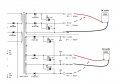
So in the schematics I saw a brake chop on one of the sheets, is it possible something was on the verge of going out and finally did. I don't know what to check because the motor still turns on and will go threw the rpms up and down, and it does stop, but it takes allot longer then it used to. This isn't a big deal if its ok for the motor to run like this. But the initial start up is so fierce that I am afraid it will harm the motor. This motor is like a 1500$ or more motor, so I don't want to fry it again. LOL Another side note, when power to motor is switched off, it doesn't start up to the last 1500 rpm setting. It starts up at 0 rpm even when start is pressed. I first thought I fried it again, but I pressed the rpm up arrow and it started to spin and climb in rpm. And before I caused all this, when power was switched on which lit up the display (motor not spinning) I would press start and it would start up to a pre set rpm which was very slow and then the user would adjust to desired speed.
So I have no clue what I did, like I said, I didn't play with any of the settings on the display. I didn't take anything apart on the motor after I put it back together. I was just using it like normal. My thought is that its something to do with the programing, because there is no soft start feature, and the initial start up after power is switched off and back to on, the motor doesn't spin at all. Like there is no initial start up value stored to tell the motor what to do when the start button is pressed. But then again like I said, I didn't change anything, this just did it by itself.
Any Ideas? I downloaded the user manual for the display/control pad if you need it.
Thanks again for all your help.
Jeremy
So I have been using it a few times now and it seems to work ok. There is a few differences/concerns I have though. First is say you are running the motor at 1500rpm and you hit the stop button. Normally the motor would instantly start slowing down kinda like downshifting in a car. It doesn't just free spin until its stops, it actually acts somehow like a brake is being applied. But now when you hit stop, it keeps spinning maybe a second or two until it finally starts the slowing cycle. Before it would actually decel the moment stop is pressed. The other issue/question is say again the motor is running at 1500rpm, you hit stop and it slows to a stop. Before when you pressed start it would slowly start up and gently rise in rmp until it reached the last rpm setting (1500 in this case) This would take approx 5-10 seconds. Now the moment you press start it races right up to 1500 lickedly split. Maybe takes a second or less.
I have tried leaving it unplugged to see if it would reset, but no luck. Also thought I would mention that the motor was working correctly, or how it used to, right after the first time we got it working. I had ran some tests and the motor functioned just like it used to. It wasn't until after the first or second time that I used the lathe that it started doing this. So I guess what I am saying is even after I reassembled the motor and wired it back up to lathe, that it was working fine the first or second time. So around the 3rd time or so it started to act this way. I didn't change programing or mess around with anything.
So in the schematics I saw a brake chop on one of the sheets, is it possible something was on the verge of going out and finally did. I don't know what to check because the motor still turns on and will go threw the rpms up and down, and it does stop, but it takes allot longer then it used to. This isn't a big deal if its ok for the motor to run like this. But the initial start up is so fierce that I am afraid it will harm the motor. This motor is like a 1500$ or more motor, so I don't want to fry it again. LOL Another side note, when power to motor is switched off, it doesn't start up to the last 1500 rpm setting. It starts up at 0 rpm even when start is pressed. I first thought I fried it again, but I pressed the rpm up arrow and it started to spin and climb in rpm. And before I caused all this, when power was switched on which lit up the display (motor not spinning) I would press start and it would start up to a pre set rpm which was very slow and then the user would adjust to desired speed.
So I have no clue what I did, like I said, I didn't play with any of the settings on the display. I didn't take anything apart on the motor after I put it back together. I was just using it like normal. My thought is that its something to do with the programing, because there is no soft start feature, and the initial start up after power is switched off and back to on, the motor doesn't spin at all. Like there is no initial start up value stored to tell the motor what to do when the start button is pressed. But then again like I said, I didn't change anything, this just did it by itself.
Any Ideas? I downloaded the user manual for the display/control pad if you need it.
Thanks again for all your help.
Jeremy