Need help choosing an op amp

Thread Starter

Andres P.

Joined Mar 6, 2015
5
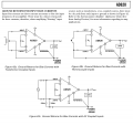
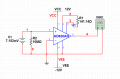
Hi. I have a situation like this where I am trying to amplify the output signal of a pyranometer sensor from 0-7.152mV to 0-2.56V so that at the end I can digitalize the signal with an ardunio's ADC. The pyranometer is the same one as mentioned before but mine gives out 4.47uV per W/m2. I am using an instrumental Amplifier (AD620AN) with a total gain of 351. The simulation of the amplification works flawlessly, as well as the wired circuit, but only when I test it with a voltage sweep and not the real sensor. My problem is, how should I connect the sensor to the amplification circuit? The sensor has three output wires: blue (low), red (high) and black (ground). I also looked at how the sensor worked and even though I didn’t understand it perfectly, I'm pretty sure it uses a thermistor circuit and some thermocouples or something. When I measure the voltage difference between the blue and red wire I get the desired 4.47uV per W/m2 ratio. I believe that the output should be treated as a thermocouple and should be grounded before entering the OpAmp. Based on some information I gathered before, I ended up wiring the sensor the way it is shown in the image 'Pyranometer OpAmp INA'. I will also attach the sensor circuit diagram of the pyranometer.

Thanks and hope to have a reply soon. Any other suggestions are also welcomed.
 

Attachments

MikeML

Joined Oct 2, 2009
5,444
Your question is about the correct application of the the pyranometer. Post the complete data sheet. Sometimes sensor makers publish "application notes" for their products.

Added:

I see that the links to the device are in Post #1 of freemyneighbor's original thread, and yes, the pyranometer should produce mV when illuminated.

Why did you ground the neg input of the instrumentation amp?
 
Last edited:

Thread Starter

Andres P.

Joined Mar 6, 2015
5
Ok, sorry Bill. I'm new to this kind of forums. MikeML, thanks for the quick reply, I wasn't expecting such a quick response. I appreciate it.

To be honest the wiring I did was because I saw it in another post someone else made. In the simulation it works, but in real life not so much. I’m not sure exactly how to connect the outputs of the sensor into the OpAmp. I'm also new to this kind of sensors. If I plug the blue and red cables directly to the negative and positive inputs respectively of the Opamp, I get a 12V output (VCC). This value is obisouly wrong. After researching some more I thought that the sensor worked like a thermocouple, so grounding one of the red or blue wires is essential. But after doing so I just receive the same output (VCC). I know my wiring must be wrong but don't know exactly why. How should I treat the sensor? Like a thermocouple or like a thermistor? or am I completely wrong??
 

MikeML

Joined Oct 2, 2009
5,444
From reading the specs of the amplifier box made by Kipp in the other thread, it seems that the pyranometer (if connected properly) should be treated as though it is a voltage source with ~ few KΩ source impedance that should be terminated by a high-input-Z amplifier. They made a big deal out of "galvanic isolation" meaning that neither wire from it should be grounded; rather it should be treated as a "floating" source.

I'm guessing that your instrumentation amp is railing because you have not provided a path for its input bias current. Unground the -input. Replace the existing 10meg with two 10megs, one connected from - input to 0V, the other from + input to 0V. The pyranometer wires go to the + and - inputs.
 

Thread Starter

Andres P.

Joined Mar 6, 2015
5
Thank you, I'll try that. Unfortunately I cannot do so until Monday but as soon as I do I'll post the results. The simulation works fine with your suggestion. I hope to obtain the same results on the real thing though. I really appreciate the help!
 

Thread Starter

Andres P.

Joined Mar 6, 2015
5
From reading the specs of the amplifier box made by Kipp in the other thread, it seems that the pyranometer (if connected properly) should be treated as though it is a voltage source with ~ few KΩ source impedance that should be terminated by a high-input-Z amplifier. They made a big deal out of "galvanic isolation" meaning that neither wire from it should be grounded; rather it should be treated as a "floating" source.

I'm guessing that your instrumentation amp is railing because you have not provided a path for its input bias current. Unground the -input. Replace the existing 10meg with two 10megs, one connected from - input to 0V, the other from + input to 0V. The pyranometer wires go to the + and - inputs.
I did what you suggested and unfortunately it still does not work. The output of the OpAmp is still VCC (12V). You said to connect two 10megs from the - input to 0V and the + input to 0V, does this mean ground? I believe the problem has to do with how the OpAmp functions and how the sensor wires must be connected (floating mode). Is there any way around this problem?

I was hopping to amplify the signal this way since it is a lot simpler and cost efficient, but on the worst case scenario I guess I would have to buy the amplifier the company offers (http://www.kippzonen.com/Product/37/AMPBOX-Amplifier#.VP1_V4XtOPI)...

There must be a way to make it work though. Before connecting the sensor to the OpAmp I tested the amplification circuit on a breadboard with a voltage sweep that went from 0 to 7.5mV. The amplified output signal had less than 1% of an error, meaning it all worked fine. The problem is within the grounding of the sensor and the amplifying circuit together. Could the two 10meg resistors connected to ground be causing unwanted noise within the OpAmp?
 

Thread Starter

Andres P.

Joined Mar 6, 2015
5
When I connect the two wires from the Pyranometer to a multimeter I get a DC signal that varies from 0 to about 5mV, depending on the sun's intensity. The sensor also works as a thermistor because when I connect the multimeter and measure resistance, it shows about 1.2252kOhms for 0mV (0W/m2). When i put it outside on the sun, the resistance increases. I was thinking of creating a Wheatstone Bridge that would allow me to obtain the W/m2 based on the resistance measured. This is just a second option since it would be a lot easier and precise if I could use the voltage difference method. This output of 4.47uV per W/m2 has been tested and calibrated by the company, using it would be ideal.

I did not use two 4.7MOhms for Rp and Rn, but rather 10Mohms for each. I don’t know if that makes a big difference. I think it might since the differential input resistance of the amplifier would then be 20MOhms instead of 10MOhms.

I attached a picture I found on the AD620 Datasheet that shows how the connections should be depending on the type of sensor or circuit you are dealing with. If I'm not mistaken, you suggested Figure 42c, the only difference is the capacitors that the image shows, the resistance values, and the squiggly lines on the wires, which I am not sure of their meaning.
 

Attachments

Top