Need help choosing an op amp

Thread Starter

freemyneighbor

Joined Nov 19, 2014
11
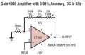
I am using a pyronometer (http://www.kippzonen.com/Product/13/CMP-11-Pyranometer#.VGztXPnF_h4 ) to measure solar radiation. The device doesn't require any power input and output a low voltage of 0-20mV in relation to the solar radiation. Industry uses a device called AMPBOX amplifier (http://www.kippzonen.com/Product/37/AMPBOX-Amplifier#.VGzuHfnF_h4) to convert this mV to (4 -20mA range ). I do not have this AMPBOX and was wondering If I could build a circuit to amplify the 0-20mV in the V range.

Any help would be greatly appreciated.
 

MikeML

Joined Oct 2, 2009
5,444
You have two separate problems: one is to amplify the mV output from the sensor to a larger voltage; the other is to convert that voltage to a 4mA to 20mA current loop signalling method. You can do this using two opamps, or with a bit of ingenuity, you can get one opamp to do both functions.

Try reading this right here on this forum...
 

wayneh

Joined Sep 9, 2010
17,496
You drive the 4-20mA loop through a shunt resistor and use an op-amp to watch the ∆V across that shunt. Suppose you drive 15mA across a 10Ω shunt - you'll see 150mV. You compare this to the amplified voltage from your sensor and adjust the loop current.

I used a separate op-amp to provide the 4mA offset at zero input voltage.

Here's the circuit I used to drive my 4-20mA LCD meter. (I didn't design it, just modded it to my purposes.) Here's the thread where I posted it, which might also interest you.
 

Thread Starter

freemyneighbor

Joined Nov 19, 2014
11
Well I don't have the AMPBOX amplifier that outputs the 4-20 mA loop...the prynometer gives out 0-20mV and I would like to either magnify that to 0-10V or 4-20mA. I have a cRIO datalogger with a +-10V analog input IO and a +-20mA analog input IO. Therefore, I need the output of the pyronometer to be in any of this range..I don't know what kinda of op-amps or circuit to produce these outputs..Im an ME trying out some EE stuff. Thanks
 

Thread Starter

freemyneighbor

Joined Nov 19, 2014
11
You drive the 4-20mA loop through a shunt resistor and use an op-amp to watch the ∆V across that shunt. Suppose you drive 15mA across a 10Ω shunt - you'll see 150mV. You compare this to the amplified voltage from your sensor and adjust the loop current.

I used a separate op-amp to provide the 4mA offset at zero input voltage.

Here's the circuit I used to drive my 4-20mA LCD meter. (I didn't design it, just modded it to my purposes.) Here's the thread where I posted it, which might also interest you.
Thanks for the feedback. Appreciate it.
 

Thread Starter

freemyneighbor

Joined Nov 19, 2014
11
Hello Mike, Sorry to bother you again...Do I need any additional circuit with XTR 117..or does it take care of outputting mA with mV inputs ?
 

MikeML

Joined Oct 2, 2009
5,444
The pyranometer data sheet doesn't specify what is the min input impedance that it's 20mV output can drive. However, the AMPBOX input impedance is 10megOhm, so it looks like you still need an opamp between the pyranometer and the TI chip. I dont have time to do it for you right now, but it is straightforward...
 

Thread Starter

freemyneighbor

Joined Nov 19, 2014
11
The pyranometer data sheet doesn't specify what is the min input impedance that it's 20mV output can drive. However, the AMPBOX input impedance is 10megOhm, so it looks like you still need an opamp between the pyranometer and the TI chip. I dont have time to do it for you right now, but it is straightforward...
The impedance is 10 to 100 ohms. Thanks Mike.
 

Attachments

MikeML

Joined Oct 2, 2009
5,444
The output impedance from the pyranometer is 100 Ohms, so that means the input impedance of the following amplifier should be much, much higher, say 1000x100 = 100K or more. This requires the use of an opamp.

The TI chip requires a minimum input voltage of 0.5V, so the opamp gain is 500mV/20mV = 25. Likely non-inverting configuration to get the high input impedance..

The opamp could be powered from the loop current via the TI chip without using a local power supply, but it would have to be a very-low voltage, low-power cmos opamp.
 

MikeML

Joined Oct 2, 2009
5,444
Here is a hack at it. Note I am using a homebrew transmitter; not the TI thing. The LM317 always sinks 4mA. The LT1077 opamp-2N3904 sinks from 0 to 16mA depending on the output of the pyranometer. Note that the loop current I(R2) is invariate with V2 going from 5 to 25V. The x-axis is the pyranometer output voltage.229.gif
 

Thread Starter

freemyneighbor

Joined Nov 19, 2014
11
Here is a hack at it. Note I am using a homebrew transmitter; not the TI thing. The LM317 always sinks 4mA. The LT1077 opamp-2N3904 sinks from 0 to 16mA depending on the output of the pyranometer. Note that the loop current I(R2) is invariate with V2 going from 5 to 25V. The x-axis is the pyranometer output voltage.View attachment 76021
I will try this circuit out. Really appreciate all the help Mike.
 

Thread Starter

freemyneighbor

Joined Nov 19, 2014
11
Hello Mike, Should I stick with the same components you have in the circuit ? LT1077 op amp is only available in China. Also R1, R2, R3 and R5 are in ohms or kohms ? Thanks
 
Last edited:

MikeML

Joined Oct 2, 2009
5,444
Hello Mike, Should I stick with the same components you have in the circuit ? LT1077 op amp is only available in China. Also R1, R2, R3 and R5 are in ohms or kohms ? Thanks
Ohms. (low values).

The opamp needs to be a rail to rail μpower cmos that can operate on any voltage from ~4V to 25V. The LT1077 does that. You should be able to find a sub.
 

AnalogKid

Joined Aug 1, 2013
10,986
First, I strongly recommend separating the gain stage from the current loop interface. And I'd look into skipping the 4-20 mA interface if possible, since your measurement system has a direct input.

A standard rule of thumb for measurement systems is that for the system to contribute minimal errors to the signal it should be at least 10 times more accurate than the error band of the sensor. Your sensor has a max non-linearity of 0.2%, which is 40 uV for a 20 mV full scale output. The 1077 is a very good part (and on the shelf at Digi-Key); I've used the quad 1079 and 2079 many times as my go-to upgrade for the LM324. But 40 uV is right at it's accuracy limit. For a system where low-level DC accuracy is critical and bandwidth is basically nothing, consider a CAZ (Commutating Auto-Zero) amp. This is like an opamp but it has a chopper-stabilized front end for microvolt accuracy and sub-microvolt drift. These used to be a pain to design with, but newer ones are fully integrated and can be dropped into many opamp circuits. The LTC1052 should work nicely.

ak
 

MikeML

Joined Oct 2, 2009
5,444
Your split supplies have three connections: -12V, 0V (sometimes called Com, or Gnd), and +12V,
+12V to pin 7,
12V t0V pin 4.
To reference the output voltage to 0V, tie pin 5 to 0V.
To provide a path for the input bias current, there needs to be an equal resistance Rp and Rn from pin2 to 0V, and pin 3 to 0V. The differential input resistance of the amplifier is Rp + Rn, so to make the input resistance 10megΩ, I would make Rn = Rp = 4.7megΩ.

If you put the pyranometer in bright sunlight, and just connect it to a Digital Multimeter in DCmV mode, what do you measure?
 
Top