Need help building delay circuit to run SPDT relay

Thread Starter

richsoucie

Joined Jan 8, 2016
19
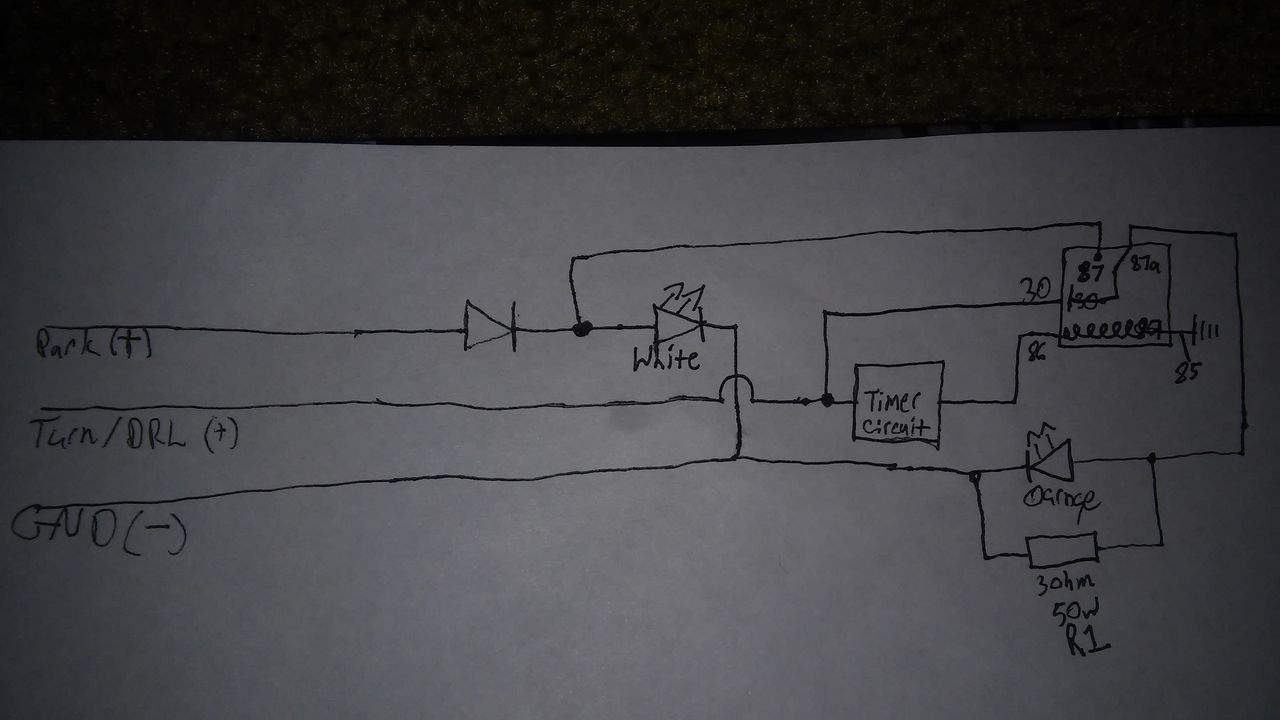
Need to build a circuit to split the turn signal and drl circuit on my car they both use the same wire and are controlled by the bcm. I have drawn up the schematic and just need help creating a delay circuit that will do what I want.

when the drl is on it supplies constant power to the wire which will be used as common on the relay and the trigger for the timer to latch the relay after 3-5 seconds
when turn signal is activated it will pulse 12v on-off until cancelled this should kill the power to the relay and cause it to unlatch

would like to use the fewest parts possible thanks for your help
 

Thread Starter

richsoucie

Joined Jan 8, 2016
19
Should have worded that different i can build the circuit i went to school for electronics but it has been 12 years since i graduated and have not really designed anything since i got out of school. What i need help with is designing the timer circuit to run the relay.
 

AnalogKid

Joined Aug 1, 2013
11,036
Your description is not clear and suffers from TMA - Too Many Acronyms. What does any of that stuff mean?

Schematic?

ak
 

dl324

Joined Mar 30, 2015
16,909
Most contributors don't mind helping people for free. But asking for someone to design a circuit for you with the fewest parts possible crosses the line between help and work. Not many are willing to work for free.

It's different if you just want help. In that case, post your circuit and your questions.
 

Thread Starter

richsoucie

Joined Jan 8, 2016
19
i have everything in the circuit except for the timer here is the diagram from when i was going to use a relay with a time delay circuit built in however i had trouble finding one that was cost effective and realized it would be cheaper to just use a regular spdt relay with a seperate timer circuit and yes i realize that my relay contacts 87 and 87a are reversed
 

Thread Starter

richsoucie

Joined Jan 8, 2016
19
the load would be the two led's the trigger would be the wire that is going to pin 86 on the relay in the diagram above. as for the delay somewhere between 3-5 seconds would be good just long enough that the turn signal wont trip the relay. The wire going to pin 30 on the relay is the wire for the Daytime running lights and turn signal when in DRL mode it gives constant power when on turn signal mode the Body control module pulses 12v similar to a flasher relay. The timer circuit would energize the relay coil after getting constant voltage for the specified amount of time and when the turn signals activate it would immediately deenergize the relay coil
 

AnalogKid

Joined Aug 1, 2013
11,036
So,,, the idea here is that turn signal signals are sent through this circuit unchanged, but you want to turn off the daytime running lights, and you are differentiating between the two signals with a 3-second timer:

1. When the wire to relay pin 56(?) is pulsing, let it pulse the relay.
2. When the wire to relay pin 56 is high for more than 2-3 seconds, remove power from pin 56.
3. When the wire quits supplying power, reset the relay holdoff timer.

- correct?

ak
 

Thread Starter

richsoucie

Joined Jan 8, 2016
19
The relay would be a single pole double throw relay.
The bulb is a switchback led with an amber and white circuit.
Parking lights are on the white circuit.
DRL and Turn are on the amber circuit.
I want to send the DRL circuit to the parking light side so they light up white activated by the delay
When the circuit loses constant power it will let the common pin30 pass thru as normal
Basically a normally open timed open
 
Last edited:

dl324

Joined Mar 30, 2015
16,909
That's an unusual configuration for a one shot; I'll take your word that it works.

I assume it's a bipolar 555 because you seem to be able to drive a relay coil, but you need to install a snubber diode to protect the timer output transistor.

The way you have the orange LED connected is strange. Normally you would put a current limiting resistor in series with the LED; e.g. 620 ohms, 1/2W or 1K, 1/4W.

The white LED doesn't have any current limiting. If that part of the circuit is connected to 12V, the LED will probably die before the series diode.

Did you get a degree in electronics/electrical engineering?
 

Thread Starter

richsoucie

Joined Jan 8, 2016
19
The led is designed to work on 12v its a dual white and amber 3157 auto bulb. The resistor is a load resistor so the computer doesn't think the bulb is out. I have added a diode and a 2n2222 to drive the relay in the newest design. The diode before the white led is to prevent the drl circuit from feeding back thru the park lamp circuit
 

withoutego

Joined Dec 22, 2015
26
How about a VFET with a cap on the gate? The relay solenoid driven by the VFET.
Bleed the cap with a resistor such that the time delay to turn-off is what you want.

I worked at a company that used VFET hot-swap switches. They tossed out a pile
of tubes of these things (IRFZ44) which I intercepted. I have a lifetime supply now.
That means every problem gets solved with a VFET
 
Top