Need circuit to enable contactor for LED driver inrush test

Thread Starter

Carolsboy

Joined Feb 7, 2018
27
I need a circuit that is 120VAC/60Hz line triggered that can be adjustable or fixed angles that will allow me to energize 24VDC contactor at peak voltage whether I am using 120VAC, 277 or 480VAC. So the circuit needs to be from 0 degrees to almost 360 to start until I can dial in appropriate angles based on contactor contact closure delay time. Once I have a good concept, I can make necessary component changes to get it to work, unless the contactor on delay time variance is too wide. I had thought about sine to sawtooth circuit to a adjustable reference comparator and latch/reset circuit, but a simple sine to sawtooth would only give 180 degrees range.

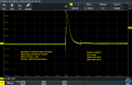
Currently using scope to capture random inrush using current probe on driver input while switching input power. Must repeat several times to capture highest inrush. Planning on building inrush fixture and would like to be able to capture peaks based on timing. I can pick the 277 line that is in phase with the 120VAC line voltage so those two tests would use the same delay, but the 480VAC test would require a different phase angle.

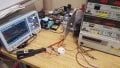
I've attached a typical inrush screen capture and a quick look at my temporary setup.

Thanks for any help offered in advance!!
 

Attachments

ebeowulf17

Joined Aug 12, 2014
3,307
Just thinking out loud here:
Zero crossing detector circuit feeding pulses to a 555 timer which triggers a latch (or maybe a 4060 configured to latch on at the end of its timing cycle.) Choose RC values to set appropriate delay. Maybe use a toggle switch to select between two resistor choices in your 555 timer so you can switch easily between the two delay times you need. There was just some good discussion on these forums within the last couple days about zero crossing detector circuits.

I have no idea how effective it would be. Just brainstorming.
 

AnalogKid

Joined Aug 1, 2013
10,987
After the contactor is closed at the desired AC line phase angle, how long does it stay closed? Do you want the circuit to cycle continuously, or is it more of a one-shot:

Edit: I just reread post #1 and see that you mention a latch and reset, so your basic idea of a ramp that is times to a power line cycle, a comparator, and a latch is correct for this sequence:

Everything off.
Turn knob to desired phase angle.
Press Start button
Starting at the next positive zero crossing in the AC line, the circuit waits the desired time before energizing the contactor.
The circuit sits with the contactor energized continuously until the Reset button is pressed.
Press Reset button.
Everything off.

The thing you missed is having a ramp (sawtooth) waveform that is started by a defined point in a powerline cycle, but not derived from it.

If this is what you want, then a *stable* linear ramp can cover an entire AC cycle and will give you a linear 5-370 degree adjustment. Note the adjustment range. Because the ramp is triggered by a zero crossing, the circuit cannot fire reliably on that zero crossing. However, it can fire reliably on the next zero crossing. For stable, repeatable, calibrated delays, the circuit will be a bit more complex than you think.

Powerline trigger generator
Set-reset flipflop
Gated constant current source
High precision polypropylene timing capacitor
Stable voltage reference
Low tempco pot
Better-than-average comparator
Contactor driver
Capacitor reset.

ak
 
Last edited:

ebeowulf17

Joined Aug 12, 2014
3,307
For stable, repeatable, calibrated delays, the circuit will be a bit more complex than you think.
That depends on the accuracy level required, right? I mean, almost any circuit could outperform the random chance of just flipping switches hoping to hit peak voltage!

Sorry, I don't disagree with you. Heck, I don't know my stuff well enough to disagree even if I wanted to. Just playing devils advocate out of habit!
 

Thread Starter

Carolsboy

Joined Feb 7, 2018
27
I am guessing the worst case scenario would be an inrush that lasts for about 10-20mS. Most of the small wattage drivers below 20W are typically 2-500uS for a 10%-10% duration while the larger 200-600W drivers are likely to have durations that last between 1-20mS depending on the switching circuit frequency and the size of the electrolytic capacitors. Some fixtures in the earlier days could have 4 or even 6 drivers. So of each driver had long duration and high amplitude inrush current, it could damage control circuits used to turn these fixtures on. I have seen drivers that operate at less than an amp of current that have over 50A of inrush... short duration may not be severe enough to tack a control relay, but the longer duration pulses that last for milliseconds will.

So my guess is that when I press the momentary start button, a phase angle timed singleshot pulse would suffice to capture the inrush profile on my scope as long as the period was say 20-40 mS long. My current random test uses a momentary NO switch to turn on the power, while a NC set of contacts are used with a 50W discharge resistor to quickly discharge the driver output. That can be altered with the new design if it works to a momentary switch can enable the singleshot and after the period is over, NC aux contacts on the contactor would discharge the driver.


After the contactor is closed at the desired AC line phase angle, how long does it stay closed? Do you want the circuit to cycle continuously, or is it more of a one-shot:

Edit: I just reread post #1 and see that you mention a latch and reset, so your basic idea of a ramp that is times to a power line cycle, a comparator, and a latch is correct for this sequence:

Everything off.
Turn knob to desired phase angle.
Press Start button
Starting at the next positive zero crossing in the AC line, the circuit waits the desired time before energizing the contactor.
The circuit sits with the contactor energized continuously until the Reset button is pressed.
Press Reset button.
Everything off.

The thing you missed is having a ramp (sawtooth) waveform that is started by a defined point in a powerline cycle, but not derived from it.

If this is what you want, then a *stable* linear ramp can cover an entire AC cycle and will give you a linear 5-370 degree adjustment. Note the adjustment range. Because the ramp is triggered by a zero crossing, the circuit cannot fire reliably on that zero crossing. However, it can fire reliably on the next zero crossing. For stable, repeatable, calibrated delays, the circuit will be a bit more complex than you think.

Powerline trigger generator
Set-reset flipflop
Gated constant current source
High precision polypropylene timing capacitor
Stable voltage reference
Low tempco pot
Better-than-average comparator
Contactor driver
Capacitor reset.

ak
 

Thread Starter

Carolsboy

Joined Feb 7, 2018
27
My first thought was zero-crossing, but the zero crossing occurs at 0 and 180 degrees. Since I want to use the circuit on the 120V and also be able to test 277V and 480V driver inrush, I am not sure if the trigger occurs every 8.3mS, if I can vary the timing enough to trigger to capture the peak voltage of a 480V driver even if one of the phases is in phase with the 120 circuit that I use to create the zero crossing pulses... I'd need every other pulse I would think, although the two phase would only be 120 degrees apart.

Just thinking out loud here:
Zero crossing detector circuit feeding pulses to a 555 timer which triggers a latch (or maybe a 4060 configured to latch on at the end of its timing cycle.) Choose RC values to set appropriate delay. Maybe use a toggle switch to select between two resistor choices in your 555 timer so you can switch easily between the two delay times you need. There was just some good discussion on these forums within the last couple days about zero crossing detector circuits.

I have no idea how effective it would be. Just brainstorming.
 

Thread Starter

Carolsboy

Joined Feb 7, 2018
27
If I had to adjust the timing using a potentiometer to dial in the correct delay to capture the peaks, it may take just as long as it would to just randomly fire the driver until I find the highest amplitude through trial and error. Using a potentiometer to begin with to find where the two periods are for 120/277 and for 480 and then using fixed components with another toggle or rotary switch could work. My biggest fear is the contactor closure time is not repeatable and therefore this whole quest becomes a moot point unless I use some high current solid state switch that has extremely low impedance so it doesn't affect the inrush current.
 

Thread Starter

Carolsboy

Joined Feb 7, 2018
27
Currently, I use the trigger level on my scope to set the expected level of the pulse. I start low until I start capturing inrush waveforms, then I increase the trigger amplitude until only amplitudes equal or higher than the last recorded amplitude are captured. It takes me about 15 minutes to set up for an inrush test and capture the peak waveforms for 3 driver samples out of the 24 driver samples we use for our component reliability test.
 

AnalogKid

Joined Aug 1, 2013
10,987
Again, a control circuit that detects only positive zero crossings and spans the entire AC cycle in one adjustment range is not difficult, it just needs attention to detail.

Separate from that, a solid state switch based on two back-to-back *large* MOSFETs will have a microsecond turn-on time and milliohms of inline resistance. Designing one is not trivial, and is not allowed on this forum because it is by definition a mains-connected circuit. There are many circuits on the web, but most of them have a single MOSFET across a diode bridge for a less complicated circuit. If your test protocol can stand two diode drops injecting a step in the AC waveform, this is a faster alternative to a contactor.

Separate from that, if you are suggesting that the circuit power the contactor for only 40 ms, I recommend against that. Once the scope has triggered and captured the first 40 ms, there is no reason to beat up both the c0ntactor and the DUT with such a short power-on cycle.

BTW, you can buy test equipment that does this kind of phase testing. Not cheap.

ak
 

LesJones

Joined Jan 8, 2017
4,174
You could generate a trigger pulse at the start of each cycle by first half wave rectifying the waveform. If you then us this half wave rectified waveform to drive the base of a transistor (Via a current limiting resistor.) you would have have a square wave at the collector. This would not be quite at the zero crossing point due to the forward voltage drop of the rectifier diode and the base emitter voltage of the transistor. You could then trigger a variable monostable from one of the edges of the square wave. Rather than trying to make a monostable that went from zero to 8.3 mS it would be easier to make one that went from 8.3 to 16.6 uS this would give you a trigger pulse at any point on the cycle. I have not been able to work out if the transient current you are trying to measure is in the contactor coil or the load current through it's contacts.

Les.
 

AnalogKid

Joined Aug 1, 2013
10,987
Rather than trying to make a monostable that went from zero to 8.3 mS it would be easier to make one that went from 8.3 to 16.6 uS this would give you a trigger pulse at any point on the cycle.
Assuming you meant ms, not us, it looks to me like it would cover only the 2nd half of the cycle. See post #3. To account for component tolerance, you want the monstable adjustment range to be one cycle plus 5-10%

ak
 

LesJones

Joined Jan 8, 2017
4,174
Hi ak,
You are correct on both points. I had seen 8.3 mS mentioned in an earlier post and checked that it was correct for half a cycle at 60 hz. The number must have got stuck in my thoughts. I apologise for repeating your suggestion from post #3 (Although you triggered from a point on a ramp it was the same method.) I had been scanning the post to try to find out if it was the contactor coil current or the load current though the contactor contacts that the TS was measuring. I was not realy looking at suggestions at the time. I was thinking that the opperating time of a contactor would be a significant part of a cycle. Oddly enough many years ago I made a thing like this for testing some reed switches that the company used in a product.

Les.
 

tindel

Joined Sep 16, 2012
936
A few points:
  1. You're obviously doing this for a company. I sure hope you haven't violated any agreements with them by making this post! I'd personally be pissed if an engineer I hired was posting questions on a public forum for all to see! How do you know I'm not a competitor of yours and looking to see how much I can learn from your pictures? Call me paranoid, but....
  2. Your current probe is probably inadequate for the job (both bandwidth and amplitude). You need one (or several) of these: http://www.pemuk.com/products/cwt-current-probe.aspx I have personally measured currents in the 100-200A range of inrush on LED driver in out of phase turn-on situations. Drivers were in the 5-25W range that I was using as well.
  3. Much of this can be calculated and/or simulated by properly modeling the input stage of the driver.
  4. The input stage of most drivers are capacitive, so inrush current is i= C*dv/dt. How the contactor (and how fast it switches) plays a humongous roll in how your inrush waveforms look when not at the zero cross.
  5. You want to switch at the zero cross if at all possible to limit your dv/dt. The higher phase from 0 and 180 degrees you are, the more inrush - end of story. The more inrush, the more susceptibility you have to blown up input stages.
  6. Switching off is just as difficult as switching on! Inductance will continue to pull current if the drivers are not PFC'd.
  7. I sure hope you're using an isolation transformer of some sort!
To get to answering your question though. I'd use a micro to sense the zero-cross somehow (google zero-cross detection), then have the micro controller drive something to turn on the contactor - probably the gate of a transistor to pull down the low side of the contactor 12V. A trim pot can then adjust the phase that you want the signal delivered in something like 50us steps.

I've been through this exercise before - can you tell?
 

Thread Starter

Carolsboy

Joined Feb 7, 2018
27
Tindel,

Yes, I work in a component reliability lab testing drivers and LED boards from various manufacturers for our light fixture design engineers to see if they will meet our warranty period... the way we test for that is what I will not discuss.

Inrush testing is added to our report just to let the design engineer know if there may be problems with multiple drivers/fixture. In the past it wasn't uncommon to have 4 or 6 LED drivers in one assembly. If each driver had 40A of inrush, you can see how this may affect a control circuit if the duration was long (over 2 mS). Nowadays, we are seeing design engineers avoid the whole inrush problem by limiting the number of drivers and also by utilizing the dimming circuits to turn lights on and off. The older dimming circuits were typically 10-100%, some still are, but there are some that are dimmable to 0%, so power can be left on the driver. There was the possibility of using negative coefficient thermistors as current limiters in the input circuit, but it involved some calculations and the net affect for that the limiting tending to reduce the peak, but spread out the duration, which isn't really a great solution.

Granted out current probe is a cheap $700 Tektronix A622, but we did do a side by side with a $4,000 current probe used with an expensive Teledyne LeCroy digital oscilloscope and had pretty good results. One problem most people seem not to consider is the power source. I have found that that you need a really good AC source that is provided through a relatively big transformer if you want true inrush amplitudes. If your power is derived from a transformer less than 1KVA, you may not achieve actual peak inrush amplitudes (loading affect).... I feel, and it is just a feeling, that the input source must come from a hefty 10KVA transformer or higher so their is no voltage sag or inductance current limiting affect that I've witnessed on even relatively small LED drivers (less than 100W).

The dricer
A few points:
  1. You're obviously doing this for a company. I sure hope you haven't violated any agreements with them by making this post! I'd personally be pissed if an engineer I hired was posting questions on a public forum for all to see! How do you know I'm not a competitor of yours and looking to see how much I can learn from your pictures? Call me paranoid, but....
  2. Your current probe is probably inadequate for the job (both bandwidth and amplitude). You need one (or several) of these: http://www.pemuk.com/products/cwt-current-probe.aspx I have personally measured currents in the 100-200A range of inrush on LED driver in out of phase turn-on situations. Drivers were in the 5-25W range that I was using as well.
  3. Much of this can be calculated and/or simulated by properly modeling the input stage of the driver.
  4. The input stage of most drivers are capacitive, so inrush current is i= C*dv/dt. How the contactor (and how fast it switches) plays a humongous roll in how your inrush waveforms look when not at the zero cross.
  5. You want to switch at the zero cross if at all possible to limit your dv/dt. The higher phase from 0 and 180 degrees you are, the more inrush - end of story. The more inrush, the more susceptibility you have to blown up input stages.
  6. Switching off is just as difficult as switching on! Inductance will continue to pull current if the drivers are not PFC'd.
  7. I sure hope you're using an isolation transformer of some sort!
To get to answering your question though. I'd use a micro to sense the zero-cross somehow (google zero-cross detection), then have the micro controller drive something to turn on the contactor - probably the gate of a transistor to pull down the low side of the contactor 12V. A trim pot can then adjust the phase that you want the signal delivered in something like 50us steps.

I've been through this exercise before - can you tell?
 

ebeowulf17

Joined Aug 12, 2014
3,307
Here is what I ended up with... circuit works perfectly with added 74HC74 dual flip flop. I have three separate optoisolators for my three different input voltages. That means I only need to make one adjustment for timing and no matter where I plug my fixture in, the voltage phase angles won't make a difference. The solid-state relay output switches within 10uS and has no switch bounce so my waveform looks perfect.View attachment 154171
Well done. Congrats!
 

tindel

Joined Sep 16, 2012
936
Thanks for sharing! Looks like it works!

Just make sure I'm following the schematic correctly: You're adjusting R9 to fire the open-loop opamp when C1 charges. The flip flops then ensure you get a two pulses before driving Q4, Q5, and your selected solid state relay. U6 then latches Q4 and Q5 once they turn on - in fact U6, Q4 and Q5 act as a single shot comparator (A trick I've used in the past as well). Releasing S2.1 resets the U6 latch.

Yeah, I'd think that will work.

One word of note. You're true inrush is higher than what you think it is - that current probe is not adequate to perform the job (Assuming you're using the A622 you mentioned before). You need a rogowski coil current probe (see link below). The A622 has poor bandwidth and inrush currents and frequencies can be very high. Again, all a factor of how fast your SSR fires causing dv/dt on your input cap(s) of your driver. In fact, I found that a i=C*dv/dt calculation would get me pretty close to the actual inrush current of the actual system. A quick spice analysis would get me within a single digit percentage (due to common mode chokes and stuff causing other variables).
https://www.google.com/search?ei=SQ.......0...1c..64.psy-ab..0.0.0....0.CPOcpHtvNVM

I actually did a similar circuit at a company I used to work for (now out of business). I used a micro though. The micro watched a opto to know when a zero cross happened. The micro then calculated how far to the next zero cross (8.3ms) from that I could then adjust to just about any phase angle I wanted to fire at with a resistor divider into an ADC. That product actually used a mechanical relay to turn on the drivers. We wanted the relay to turn on and off at the zero cross to limit dv/dt during turn on and di/dt at turn off. There are a couple of modes that are important to understand to make this work, but we eventually did it and we were seeing mechanical failures of the relays before we saw electrical failures. We were essentially turning the relay on/off into no load!
 

Thread Starter

Carolsboy

Joined Feb 7, 2018
27
Thanks for sharing! Looks like it works!

Just make sure I'm following the schematic correctly: You're adjusting R9 to fire the open-loop opamp when C1 charges. The flip flops then ensure you get a two pulses before driving Q4, Q5, and your selected solid state relay. U6 then latches Q4 and Q5 once they turn on - in fact U6, Q4 and Q5 act as a single shot comparator (A trick I've used in the past as well). Releasing S2.1 resets the U6 latch.

Yeah, I'd think that will work.

One word of note. You're true inrush is higher than what you think it is - that current probe is not adequate to perform the job (Assuming you're using the A622 you mentioned before). You need a rogowski coil current probe (see link below). The A622 has poor bandwidth and inrush currents and frequencies can be very high. Again, all a factor of how fast your SSR fires causing dv/dt on your input cap(s) of your driver. In fact, I found that a i=C*dv/dt calculation would get me pretty close to the actual inrush current of the actual system. A quick spice analysis would get me within a single digit percentage (due to common mode chokes and stuff causing other variables).
https://www.google.com/search?ei=SQ.......0...1c..64.psy-ab..0.0.0....0.CPOcpHtvNVM

I actually did a similar circuit at a company I used to work for (now out of business). I used a micro though. The micro watched a opto to know when a zero cross happened. The micro then calculated how far to the next zero cross (8.3ms) from that I could then adjust to just about any phase angle I wanted to fire at with a resistor divider into an ADC. That product actually used a mechanical relay to turn on the drivers. We wanted the relay to turn on and off at the zero cross to limit dv/dt during turn on and di/dt at turn off. There are a couple of modes that are important to understand to make this work, but we eventually did it and we were seeing mechanical failures of the relays before we saw electrical failures. We were essentially turning the relay on/off into no load!
The A622 current probe is rated to 100KHz (-3db)... that's a 10uS response. The driver inrush periods we are measuring are typically 50uS to 3mS. The small drivers have the quickest, but lowest amplitudes, so I think the waveforms we are getting are not too bad.
 

tindel

Joined Sep 16, 2012
936
Quick math:
Assume a 4.7uF input capacitance, typical of a LED driver pi-filter input stage in the 30W class
Assume a SSR with a 10us turn-on time (a bandwidth of only 35kHz):
120Vac => 170V peak
i = C * dv/dt = 4.7*uF * 170V/10us = 80*A

Don't forget that -3dB at 100k is ~70%. Add to this that the derating of the A622 is derated to ~17A at 100k (figure 7) so your measurements are unreliable above 17A, and you could be damaging your probe to boot! http://w140.com/tek_a622_instructions.pdf

The numbers don't lie, and I'm not lying to you - your current is higher than what you're measuring. Don't get sidetracked by the lower frequency stuff (which is probably being measured correctly, but is less important). What you want to really know is the peak of that single pixel wide pulse at the beginning of turn on in your scope plot. Do you have another scope plots of this? That's you're surge current under worst case conditions - not the lower current/frequency stuff.

I'm not trying to be a jerk or shit on your parade (In fact, I like your solution and think it's doing the job well). I'm just trying to help educate you and anyone else that might read this. Please, do yourself a favor and at least demo a rogowski coil and look at the differences yourself. There are several vendors out there and they aren't that expensive at a corporate level. You may already have one (or several) laying around if you ask around. It will be worth your time.

At the very least do the math to find out what current you expect to see given your SSR turn-on time, operating voltage, and input capacitance and use this to double check your measurement.
 

Thread Starter

Carolsboy

Joined Feb 7, 2018
27
Quick math:
Assume a 4.7uF input capacitance, typical of a LED driver pi-filter input stage in the 30W class
Assume a SSR with a 10us turn-on time (a bandwidth of only 35kHz):
120Vac => 170V peak
i = C * dv/dt = 4.7*uF * 170V/10us = 80*A

Don't forget that -3dB at 100k is ~70%. Add to this that the derating of the A622 is derated to ~17A at 100k (figure 7) so your measurements are unreliable above 17A, and you could be damaging your probe to boot! http://w140.com/tek_a622_instructions.pdf

The numbers don't lie, and I'm not lying to you - your current is higher than what you're measuring. Don't get sidetracked by the lower frequency stuff (which is probably being measured correctly, but is less important). What you want to really know is the peak of that single pixel wide pulse at the beginning of turn on in your scope plot. Do you have another scope plots of this? That's you're surge current under worst case conditions - not the lower current/frequency stuff.

I'm not trying to be a jerk or shit on your parade (In fact, I like your solution and think it's doing the job well). I'm just trying to help educate you and anyone else that might read this. Please, do yourself a favor and at least demo a rogowski coil and look at the differences yourself. There are several vendors out there and they aren't that expensive at a corporate level. You may already have one (or several) laying around if you ask around. It will be worth your time.

At the very least do the math to find out what current you expect to see given your SSR turn-on time, operating voltage, and input capacitance and use this to double check your measurement.
I know the better current probes are thousands of dollars and I have noticed the expensive ones are also less susceptible to emi generated near the probe body. Since we do have better probes and scopes, I will do a comparison of a couple drivers when I complete the test fixture. Thanks for your help. I will post the screenshots when I compare the probes.
 

tindel

Joined Sep 16, 2012
936
Note that rogowski coils are really not that expensive - I think we bought two at ~$1500 each not long ago (unfortunately the company tanked a few short months later). This is really chump change when working at a large corporate company, as I believe you are. I also had to demo one to convince the boss that I needed one to get the job done properly before he'd shell out the cash. I thought that was a reasonable request. It was an easy sell once he saw the side-by-side comparison.
 
Top