Need Advice on Removing Relay on PCB

dl324

Joined Mar 30, 2015
18,376
dl324: (1) You say "There's nothing wrong with your relay." Are you suggesting I melt solder into the hole and it'll work?
I never said that. It was two other members.

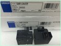
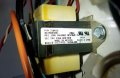
It always looked to me like one lead from the relay contacts had been burned up and that you were going to be replacing the relay.

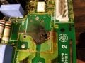
It looks like there are traces on both sides of the board to carry a large current. If the plated through hole on the burned region has been damaged, you're doing to need to do something to make a high current connection between the top and bottom layer traces.
 

dl324

Joined Mar 30, 2015
18,376
Would anyone endorse my original idea in my very 1st post?
I wouldn't. The traces on the board are sized for a large current. If it's anywhere near 30A, you're going to need #10 wire. With that much current, any unnecessary resistance is going to cause problems; as evidenced by the burnt spot on the board and the missing relay lead.
 

MaxHeadRoom

Joined Jul 18, 2013
30,693
My conclusion after replacing many of these such relay's used in appliances, the current through the small pin causes degradation of the soldered connection and eventually the high resistance result ends up with a blown pin or trace.
What ever method you use, reinforcing this connection usually cures the problem.
Max.
 

Thread Starter

tony17112acst

Joined Jul 20, 2018
31
dlc: Something you may not know that I left out: the large current is completely irrelevant when using the exact relay but with terminals instead of pins/leads. It's because that large "traces" (I hope I'm using that word right) simply lead to 2 terminals just to the left (in the photos). These terminals would be obsolete because the new relay would now have the terminals directly on it instead of it running through the PCB.

If you look at the very 1st photo of this post - the pink and orange wires are connected to the terminals that run to the leads/pins of the relay. If I used an exact replacement relay with terminals instead of pins, then the pink and orange wire would connect directly to the new relay. The need for the 240VAC traces in the PCB would no longer be needed.

What do you think?
 

Attachments

Thread Starter

tony17112acst

Joined Jul 20, 2018
31
dl324: Is your reference to a risk of fire referring to the 24VDC wires or the 240VAC connections?

The 240VAC, 30A terminal connections are far superior to the original pins/leads on the PVC because the wires that use the relay would be tailor made/fitted to attach to the terminals on the relay itself. So if you're referring to the 240VAC part, I'm may be missing something. Because I didn't think running 24VDC wire from the coil terminals of the relay to the PCB isn't a fire risk. But maybe I'm missing something there too?

Another way to put it: If I had to guess which has less resistance of 240VAC, 30A current running through:
(1) The wire's terminal <-->THRU<--> PCB terminal <-->THRU<--> PCB traces <-->THRU<--> repaired copper braid <-->THRU<--> lead/pin on replay
vs.
(2) The wire's terminal directly connected to the relay's terminal
...Unless I'm missing something, wouldn't #2 indisputably have less resistance?

The OLD relay uses the PCB to provide the terminals needed for the heater wires, but the NEW relay has the terminals RIGHT ON IT - eliminating the need for the current to flow through the PCB. The heater wires would connect directly to the relay! I hope I'm not missing something here.

Thanks for all your help!!
 
Last edited:

SLK001

Joined Nov 29, 2011
1,549
Here's the results for my task from last weekend. This is a relay board from an electric oven. This was the third time I've had to fix this guy. The first time, all I did was resolder the pin, thinking that if that's all the manufacturer did, then it was good enough for me. The second time, I added the copper wires crimped tightly to the pin (don't remember why I didn't do all of them this way). The third time, I finished adding copper wire to all the high current pins. This first pic shows an open relay pin in the big pad second from the right. Fortunately, the pin is still intact.

before.jpg
This is the post repair photo. All the high current pins now have extra copper to carry the current.

after.jpg

This happens because the hole for the relay is too big. Because it is too big, solder is carrying a load over a distance that is beyond its capability, thus heating up and melting away. As the last of the solder breaks the connection, an arc usually occurs that seriously blackens the board and the pin. If you're lucky, the PTH is still intact, but the arcing can wreck havoc with them and the corresponding component pin.

Back to the original problem. Do not try to replace the relay with anything other than the original type. To leave it hanging like you propose is dangerous. With the same type of relay, you will not need any Z-wires, since top to bottom connections are already made. Once installed, take your copper reinforcement and add copper from the pin to the terminal (you will have to scrape away some of the solder mask). Once you repair the board like this, you shouldn't have anymore problems with it.
 

ebp

Joined Feb 8, 2018
2,332
If you use the TE relay you will have to make a connection back from the relay power terminal to where the burned pin was for what is presumably a "sense" input of some sort (the narrower trace from the burned hole to one of the power resistors. This could be done with small gauge wire, provided it has the required insulation voltage rating. It does mean having to remove the female connector from the orange wire to add the extra conductor. You need good quality connectors and a good crimping tool for reliability.

The connections to the coil don't need to be particularly short and can again be made with small wire with adequate insulation rating (even though they are "low voltage" an presumably isolated from the AC line by a transformer somewhere, it is generally bad practice to mix high voltage and low voltage wiring in close proximity without using "high voltage" insulation on both).
 

Thread Starter

tony17112acst

Joined Jul 20, 2018
31
SLK001: Nice! thank you for the photos explaining how the extra wire works!! That explains a lot! Also, FYI, I would never suggest leaving a mounted relay hanging or dangling (I hope I did not). Also, the proposed replacement relay with terminals instead of PCB pins has the same specs as the original, even down to the # of ohms for the low side coil (24VDC). Compare the data sheets of the two relays if you have doubts, the model #'s are listed above somewhere - just an FYI. But don't hesitate to point out something I'm missing that would be a bad idea!

ebb: OMG, it sounds like you understand what I might do with the replacement TE relay that has terminals instead of leads/pins!! To me, there's nothing more safe AND more robust than the high voltage wires connecting DIRECTLY to the relay's terminals vs. unnecessarily running that high voltage through the PCB (assuming the replacement relay has the exact same specs except having terminal receptacles instead of PCB pins/leads). In fact, running that high voltage through the PCB is what caused this failure in the first place. But you bring up a new matter: I forgot to consider that the current ALSO runs to that resistor! Thank you for pointing that out. I could run another wire to the old (burnt) hole to send voltage to that resistor (as you correctly suggested), but I think I'd just spend the $5 on ebay for the version of the original relay with terminals AND pins: the Omron G8P-1A4TP (see photo).
 

Attachments

Last edited:

MaxHeadRoom

Joined Jul 18, 2013
30,693
Sounds like you have it all sussed out, but if you still want to heed the advice I posted in #7, the relay you linked to also has a vent nib you may want to consider opening, reduces contact arcing due to ionization in a sealed relay.
Here is a an explanation.
Max.
 

Attachments

ebp

Joined Feb 8, 2018
2,332
That relay is definitely the best solution, in my opinion. Don't forget to put some sort of decently-robust insulation over the unused quick-connect tabs on the PCB.
 

Thread Starter

tony17112acst

Joined Jul 20, 2018
31
Thanks Max! I will; I own the commercial coin-op dryer, so I want to do the job right; even better than the original design.

ebp: Thank you on that too, I actually thought of that.

So, I got an answer on the glue/flux - my original question was how to remove the relay once it's desoldered - because it looks like it's glued See previous photos). Several suggested that it's flux. But yesterday I had the chance to run some denatured alcohol over the amber substance in question and it didn't do a thing! No softening/gumming or dissolving - nothing. I put a blade to it after letting the denatured alcohol sit on it for about a minute, and it's as hard as normal.

So I could possibly run a blade through 2 of the sides, but could never get on the other 4 sides with a blade since it's so close to other resistors, etc. (see attached photo).

I'm waiting for the braided copper to arrive since I need that to remove the solder, and the new relays (to arrive). But I may never get that old relay off. So I'm not sure what to do at this point.
 

Attachments

Last edited:

MaxHeadRoom

Joined Jul 18, 2013
30,693
One scenario if you have one is to try using a Dremel with a pin point router end, if you can get it in, just be very careful on the depth, but the one I have is quite fine, I have used them in the past for a similar application.
Max.
 
Last edited:

SLK001

Joined Nov 29, 2011
1,549
If it is glued down (since it's a commercial use product, it might be, but there really is no reason to glue parts on a one-sided board), use a heat gun to heat the board to around 150°F. That will soften 99% of all adhesives.
 

Thread Starter

tony17112acst

Joined Jul 20, 2018
31
OK, My plan is to de-solder the old relay and then try to cut that bottom glue off, knowing I may have no angle to get to the glue in the super-tight areas. Then solder in the replacement relay which is an exact copy of the old but with terminals on the top in addition to the normal 4 pins/leads on the PCB side.

I am waiting for the relays to be delivered (I have 3 different ones coming for maximum options), but I will surely give an update with my results ...or for more help getting that relay off - haha.

I am very thankful for everyone's help on here. This is important to me because a new board costs around $700 and a used one about $200, so this $5 relay will save me a lot and you all have helped make it happen. I know that sounds like a cliche' but you all are very admirable helping a novice like me out!

-Tony
 

Thread Starter

tony17112acst

Joined Jul 20, 2018
31
My copper braid just came in and I immediately tried to de-solder and after my 1st try ....

I GOT IT OFF!!

I used a razor blade to cut into the side that was easy to get to. Then I put a very thin and small screw driver under it and pried around. It was risky, knowing that the solder may still be holding it on, but there was always progress, so I kept going and thank goodness the copper DID get all the solder up.

The amber stuff was indeed not too thick and wasn't as strong as I thought it might be.

Now all I need to do is wait for the relay with PCB pins and terminals to get here from China and I'll be soldering it on! Do I even bother dropping solder on the blown-out hole? ...knowing the terminal wire will be connecting directly to the relay's terminal instead of the PCB pin?

EDIT: Wait, I do because the current needs to reach the resistor trace on the underside.
 

Attachments

SLK001

Joined Nov 29, 2011
1,549
The amber stuff may be some type of conformal coating. Acetone may remove it. I would be hesitant to replace the relay with anything other than an exact replacement, but if you do, make sure that there are no other connections from the terminals except to the relay. If there are others, you might need more mods than you thought. If you replace the relay with a like one, then use the copper braid to bridge the top and the bottom and solder that in prior to placing the relay, then solder the relay.
 

Thread Starter

tony17112acst

Joined Jul 20, 2018
31
UPDATE (Now I'm really frustrated):

Since I already had the TE replacement relay with all 4 terminals on the relay (no PCB pins), I decided that it would allow me to do the job without having to solder copper braid or any wires to the blown-out barrel hole on the PCB which is unreliable in the 1st place.

But now I have 2 NEW major problems, which seem totally unrelated to the relay:

(1) When calling for heat, I am now NOT getting 24 volts from the PCB where I soldered the new wires (which tells the relay to activate). I even scratched off some of the green protector off to test for 24v right on copper on the board itself and the 24V is not there (see photo).

(2) The dryer drum now spins simply when the door is closed and with no coins inserted. There is a Start button to be pushed to start; it shouldn't start by closing the door.

What makes this weird is that this DID NOT happen when the relay was bad before I removed (de-soldered) the relay. Currently the relay has nothing to do with this; it's not even attached ...and doesn't need to be. All the relay does is close the circuit to the 240v heating element and sends it to a resistor(?) which shouldn't matter because when the old relay was on and no 240v was passed to it, these 2 problems did not exist. So these 2 problems started by me simply removing (de-soldering) the old relay.

Does anyone have any ideas why this changes simply from me removing the old relay? I know this is not a dryer troubleshooting forum, so it's not a big deal if no one does. I am close to surrendering to buying a used control board on ebay for $150 to get running, but replacing the relay isn't complicated so it would sure be a bummer if I had to go that route.

Honorable Mention Mystery: When I tested the transformer to make sure it was sending 24v out, it registered nothing on DC volts. Then I looked at the transformer and it looks like 24v AC, so it DID measure 24v AC! HOW?! The original relay is labeled 24VDC! I even tested the relay with DC from an 18 volt battery and it worked. So how can 24VAC turn a 24VDC relay on?
 

Attachments

MaxHeadRoom

Joined Jul 18, 2013
30,693
A standard transformer only delivers AC, it requires some device to convert to DC, usually a bridge.
There must be something else to the plot, the DC does not require any capacitor if only inductive devices are used such as a relay etc.
I would also clean off and re-solder any other suspicious looking joints.
Max.
 

Thread Starter

tony17112acst

Joined Jul 20, 2018
31
Max, thanks. You say "I would also clean off and re-solder any other suspicious looking joints." ...that's what I thought too, but that's why I scraped off the copper protector on the PCB to test for voltage independent of my 2 new wires that come later down the line. If 24v is being sent to the old relay and all I did was remove the relay, there should still be 24v being sent ...that's what I don't understand, but obviously, something's wrong ...seemingly with something I didn't touch.
 
Top