Need Advice on Removing Relay on PCB

Thread Starter

tony17112acst

Joined Jul 20, 2018
31
Hi Everyone,

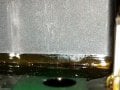
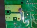
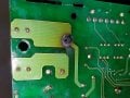
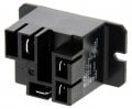
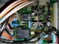
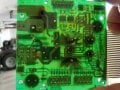
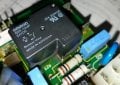
I'm a novice and I need to remove the Omron G8P-1A4P relay on this coin-op dryer board (see photo). But I see there's an amber varnish or something holding it fast to the PCB (maybe to water-proof?). I have seen answers on how to do this on this site - to just cut it off after desoldiering it. BUT if you look in the photo, there's no way to get a knife in several tight spots (not just one).

Any ideas that I can try? Thanks in advance!!

P.S. I just ordered an exact replacement and a 2nd replacement that has terminals on it (the TE T9AP1D52-24) in case I need to improvise, So I COULD leave the old one on and soldier wires to the 24VDC pins on the back side and mount it somewhere, but I don't know if the 24 volts (or amps, I guess) needed would drop too low to activate it since the old one would be pulling juice too.
 

Attachments

dl324

Joined Mar 30, 2015
16,845
Welcome to AAC!
if you look in the photo, there's no way to get a knife in several tight spots
I don't see what you're talking about. I see yellow stuff, but it's on more than just the relay.

I'd try unsoldering all of the pins and seeing if heat from a hot air gun would make it release.

I COULD leave the old one on and soldier wires to the 24VDC pins on the back side and mount it somewhere, but I don't know if the 24 volts (or amps, I guess) needed would drop too low to activate it since the old one would be pulling juice too.
I'd be more concerned about the 30A contact rating.
 

jpanhalt

Joined Jan 18, 2008
11,087
If that PCB has plated through holes, be very careful pulling it off. You might pull the pad and hole plating too. Then, you will have a problem!

If you have a hot air soldering device, then you can heat multiple pads at one tine and get it removed safely. If you are skillful with a propane torch, that will work too. I assume you don't or aren't.

An alternative is to get a very low melting point solder (i.e., a little more than 100°C). Clip each joint as close to the board as you can. Add the solder to form an alloy. Suck it up with solder brad, and add more. Then, you should be able to remove it with an ordinary hairdryer. Chip Quik is one brand of such solders.
 

ebp

Joined Feb 8, 2018
2,332
I'm pretty certain the yellow stuff is just residual flux from the original wave soldering of the board (the board goes through a flux wave to coat the bottom, but some often makes it to the top surface, then though a molten solder wave that takes off most of the flux from the bottom but leaves any that got to the top). Modern conformal coatings usually are nearly colorless. Flux will have very little mechanical strength and shouldn't impair parts removal.

Parts like that relay are hard to remove. Fortunately, it looks like all of the connections are made via copper on the solder side of the board, so even if you damage the plated "barrels" in the holes it won't prevent soldering in a new relay and having it work OK.

A propane torch is a very risky thing to use unless you have carefully worked out the method on scrap boards. It is far to easy to burn and blister the board. Without specialty equipment, solder wick is probably the most workable thing to try. Sometimes after clipping the pins flush with the board you can go around and around from pin to pin remelting and pulling, slowly getting each pin free a fraction of a millimetre at a time. You can pull the plating out of the holes doing this, but again I don't think that is any sort of disaster for that board. A hot air tool can be very helpful, even if all you use it for is to preheat the area. This will help keep the solder molten longer. The low melting point solder is useful, but you may have trouble finding it locally.

Another alternative is to try to cut open the relay case with a rotary tool, but you don't want to slip and it is messy and time consuming. You don't want metal swarf getting on the board. If you do get it open you might be able to clip the pins very near the circuit board. If you try this approach, don't clip the pins on the solder side so you have something to grip with pliers while the solder is molten. I think that relay is sealed, so pins are held in place with epoxy that won't want to give them up easily. I'd consider this only in desperation.

You will probably need to repair the connection to the burned hole using some copper wire soldered around the relay pin and to the adjacent foil. Carefully scrape some of the green solder mask off so you get exposed copper (which might have tin or solder plating). Wire of about 22 AWG should be OK. You may just need to carefully scrape away the charring.

My guess is that the original failure was due to a poor solder joint at that pin.

Good photos!
 

MaxHeadRoom

Joined Jul 18, 2013
28,619
The replacement is available at Digikey.
You need at least dry-wick desoldering or better still a solder sucker.
I generally use the copper wick to re-inforce the current carrying traces upon installation of the new relay.
Max.
 

SLK001

Joined Nov 29, 2011
1,549
The yellow stuff is just flux. Since it is a double sided board, I would use a heat gun to first heat up to board to about 180°F, then use a soldering iron and copper wick to remove the solder. If the solder is Pb free, I would first add leaded solder to lower the melting point of the Pb free - makes everything easier to accomplish.

These relays are fairly robust. What makes you think that it is the relay that is bad?
 

MaxHeadRoom

Joined Jul 18, 2013
28,619
It looks to me like the typical problem seen with these relays, the solder around the pin deteriorates and eventually opens up the pin connection.
This is the reason I use the solder wick to re-inforce the pin to copper connection creating a much higher current plane/connection.
Also on these relays, the vent pin is left closed due to fluxing etc, it pays to open them up when fitting a new relay.
Max.
 

SLK001

Joined Nov 29, 2011
1,549
It looks to me like the typical problem seen with these relays, the solder around the pin deteriorates and eventually opens up the pin connection.
This is the reason I use the solder wick to re-inforce the pin to copper connection creating a much higher current plane/connection.
Also on these relays, the vent pin is left closed due to fluxing etc, it pays to open them up when fitting a new relay.
Max.
Looking closer at the back of the board, I see that you are correct.

To the OP, THERE IS NOTHING WRONG WITH YOUR RELAY. The solder used to attach the relay to the PCB has melted away (solder isn't a very good conductor). The best way to fix this is to attach copper over the pin and solder that to the PCB. I use 14-16 gauge house wire, but solder braid will also work. Create a solid mechanical joint around the pin, then solder.

I have a Kenmore oven that has this same issue that I have to fix tomorrow.
 

Thread Starter

tony17112acst

Joined Jul 20, 2018
31
Thanks everyone for your input! Although info on de-soldering is great, it's not my original question.

My original question is: once the relay is de-soldered, how do I get it to release from the varnish/glue on the bottom that will be holding it on? ...not how to de-solder.

I've attached another close up photo of how the relay is glued on there. That glue/varnish goes ALL THE WAY AROUND the entire relay.

dl324: what do you mean by: "I'd be more concerned about the 30A contact rating?"
ebp: I wont use a torch, nor a heating gun. I did see a video on scraping the green off to solder wire on to it, so I could do that (if I get the relay off)
MaxHeadRoom: As I mentioned, the parts have already been ordered. But on your other post - if I replace the relay myself, I'll ask you about how to vent the new relay, I don't understand it right now.
SLK001: I know it's bad because: (1) I get no voltage on the other side of the relay when it's activated, (2) When I bypass the relay, everything works fine, (3) There's a gigantic burn hole on the back side of the relay to boot (see photos of original post).

Everyone's tips on desoldering points out how to avoid pitfalls, which is great, but also has me wondering if I should just pay to have it removed. I found a service on ebay for $45 to replace it:
https://www.ebay.com/itm/Repair-Service-for-a-Speed-Queen-MDC-Control-Board-2163-RSPC-P-N-511867/292595600991?hash=item44200e8e5f:g:Nw8AAOSwF25bGY6t&_sop=15&_sacat=0&_nkw=511867+control&_from=R40&rt=nc

...so I'm undecided at this point. I have desoldered before, but this time that varnish makes it look impossible to get to. thanks!
 

Attachments

dl324

Joined Mar 30, 2015
16,845
I have desoldered before, but this time that varnish makes it look impossible to get to.
If it was me, I'd try removing the relay. It looks easy enough. Then find out if what you think is adhesive is really adhesive. If it is, heat it to see if it will release.

A hot air gun would be best because you can use a small nozzle. In a pinch, you could try a paint remover or hair dryer with an appropriate nozzle to direct the air.

upload_2018-7-20_17-10-25.png
The two leads above and below the red circle on the right are the coil. It looks like the two blobs of solder in the red circles are on pads with no leads (no idea why they're there). The pad with the yellow circle looks empty. If there's a lead there, as two posters think, you can try cleaning the residue and resolder; using some wire braid to give a better electrical connection.
 

ebp

Joined Feb 8, 2018
2,332
I still think it is just flux around the relay, and from the strong yellow color I suspect a fairly ordinary rosin-based type.

To test, you will need a solvent that will dissolve the flux. Depending on where you live either 99% isopropyl alcohol or 95% "denatured" alcohol should be a common drug store item. Either will dissolve flux quickly but have much slower effect on any kind of conformal coating or adhesive. There are all sorts of flux removers available, but many of them will also be fairly aggressive against other things.

Moisten a cotton tipped swab with some alcohol and have a gentle go at the yellow goop. If it some of it comes off easily it is flux.

The other thing you can do is heat it with a hair dryer. Flux will soften and become tacky at fairly low temperature whereas adhesives are more likely to stay hard.

[EDIT] You could also try chipping off a bit around the base of the relay and try dissolving it in alcohol. Regardless of whether it is flux or an adhesive, if it dissolves you could very cautiously use alcohol to remove it.
 

SLK001

Joined Nov 29, 2011
1,549
The hole looks empty to me...
Didn't see that it was missing a pin. Since the 30A line is on the top (under the relay), the PTH is probably toast. This means that the OP will have to use a couple of Z wires to connect the two sides.

The chances of that goo seen on the top being adhesive is slime to none. It is way to expensive to use for a parts-only-on-one-side board. It's flux... trust me.
 

MaxHeadRoom

Joined Jul 18, 2013
28,619
What I have found with these relays and a common problem, is the solder joint on a power pin eventually degrades and either blows the pin or the adjacent copper.
Hence the copper braid repair.
I think if you remove all the solder joints on all pins, solder sucker etc, then it will lever off the flux, small screwdriver etc, if replacing the relay then if damage to the relay occurs it is no loss.
Max.
 

Thread Starter

tony17112acst

Joined Jul 20, 2018
31
dl324: (1) You say "There's nothing wrong with your relay." Are you suggesting I melt solder into the hole and it'll work? I don't see how since the 30 amp pin looks like it blew away. But I'm willing to try since it's going to be removed anyway. We're talking 240 volts AC, so I don't know if it's a good idea, but sould I try it? (2) I have no tools like a hot air gun; just a 30 watt iron with some solder with flux built in. (3) You say "using some wire braid to give a better electrical connection" ...what's wire braid? It's not the flux infused copper braid to remove solder is it?

ebp: GREAT suggestions ...thank you! I will try tomorrow.

SLK001: When you say use Z wire ...what is a Z-wire?

Sorry, as I say I am new to this, but have done simple stuff before. I have attached a bigger photo of the blown pin. It's 30A and 240 VDC ...it feeds a dryer heating element so it's a ton of juice going through this tiny pin.
 

Attachments

Thread Starter

tony17112acst

Joined Jul 20, 2018
31
SLK001: You think the relay is still good ...I assume I can run 24 VDC to the coil pins and listen to see if it clicks inside and maybe even test for continuity in the blackened hole and the other terminal.
 

Thread Starter

tony17112acst

Joined Jul 20, 2018
31
Would anyone endorse my original idea in my very 1st post? ...to leave the old relay on the board and use a new relay with 4 wire terminals instead of PCB pins. I would mount it inside the dryer panel and run the coil wires to the 24VAC pins under the PCB.

This would accomplish 2 things:
(1) It eliminates any flimsy connections using solder to run a 240VDC, 30A through these small pins;
(2) It eliminates me screwing up the PCB since this is my 1st time doing something like this.

I have ordered the relay with terminals just in case: the TE T9AP1D52-24 (see photo).
 

Attachments

MaxHeadRoom

Joined Jul 18, 2013
28,619
Personally I would use the right relay and do the power pin/plane reinforcing, it does lasts in my exerience.
But if you already have that relay then ensure the connections to the stake-on connector are good.
I would mount it as close as possible to the board.
Max.
 
Top