Need a momentary 12V output

Thread Starter

yazen

Joined Jul 11, 2011
24
Hello all:

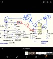
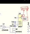
I am helping my uncle with his car, the side mirrors fold when you push a button. I am needing something (relay, or a circuit) that produce a 12V for a second when the car is started, so I hook it up to a SPST relay, and the relay will be connected to the fold mirror button.

The issue I am facing is that, I want the relay or circuit to produce a 12V when the car starts, and when the car is shut off, so it energizes the relay once again and the fold mirror switch is pushed to fold mirrors.

Any ideas or guidance are highly appreciate it.

Thanks,
Yazen
 

ElectricSpidey

Joined Dec 2, 2017
2,779
Two relays and a 555 should do the job.

The first relay is wired to trigger the 555 when the accessory line is active, then triggers the 555 again when the accessory line disconnects.

The second relay is powered by the 555 and is connected to the mirror button.

If this sounds good I can provide more details.
 

crutschow

Joined Mar 14, 2008
34,428
Below is the LTspice simulation of a circuit that should do what you want:
The CD4093 quad Schmitt-trigger NAND gate single package is configured as an XOR gate that gives a pulse on both the leading and trailing edge of the input.
The relay (red trace) turns on for about 1 second when the ignition switch voltage (green trace) goes both high and low.

The battery power (Vb and Vdd) must be applied to the circuit continuously so it has power when the ignition switch voltage goes low.
It takes only a very small leakage current when quiescent, so will not drain the battery.

1634932431432.png
 
Last edited:

Thread Starter

yazen

Joined Jul 11, 2011
24
Two relays and a 555 should do the job.

The first relay is wired to trigger the 555 when the accessory line is active, then triggers the 555 again when the accessory line disconnects.

The second relay is powered by the 555 and is connected to the mirror button.

If this sounds good I can provide more details.
Yes, this is exactly what I need. Please do so when you can.

Thank you,
Yazen
 

Thread Starter

yazen

Joined Jul 11, 2011
24
Below is the LTspice simulation of a circuit that should do what you want:
The CD4093 quad Schmitt-trigger NAND gate single package is configured as an XOR gate that gives a pulse on both the leading and trailing edge of the input.
The relay (red trace) turns on for about 1 second when the ignition switch voltage (green trace) goes both high and low.

The battery power (Vb and Vdd) must be applied to the circuit continuously so it has power when the ignition switch voltage goes low.
It takes only a very small leakage current when quiescent, so will not drain the battery.

View attachment 250778
Thank you for the prompt response. Appreciated it.

Yazen
 

Thread Starter

yazen

Joined Jul 11, 2011
24
No point in me posting anything now.
Apologies for the confusion. I wanted to go with your suggestion, I find it easier to accomplish.

Nothing wrong with what crutschow suggested, I just wanted with what I am more comfortable with.

I do appreciate both of you.

Yazen
 

Thread Starter

yazen

Joined Jul 11, 2011
24
How is that?
I am a beginner when it comes to circuits. So I am afraid what if I mess things up.

I'd love to build a complex circuit like the one you designed if you could assist me with a list of parts and be patient with my stupid questions while I build it.

I honestly have been researching your design online to learn more about it. And I think I like to build both, yours and his.

Do you think you can share with me the list of components that I need to build it please? Also, don't I need to print a board first? so I solder all the parts on it? or use a plain one?

What is VB?

Why connect it to VDD?

Again thank you very much to both of you for your assistance.

Yazen
 

crutschow

Joined Mar 14, 2008
34,428
list of components that I need to build it please?
Yes.
Where would you buy the parts?
don't I need to print a board first? so I solder all the parts on it? or use a plain one?
You can use a Vector (perf) board which has holes to mount the components
Some have a copper grid to make it easier to wire.
What is VB?
It is the battery voltage.
Why connect it to VDD?
Vdd is the battery voltage filtered by C2 and R4 to minimize voltage spikes that can occur on the vehicle battery voltage..
 

Thread Starter

yazen

Joined Jul 11, 2011
24
Yes.
Where would you buy the parts?
You can use a Vector (perf) board which has holes to mount the components
Some have a copper grid to make it easier to wire.
It is the battery voltage.
Vdd is the battery voltage filtered by C2 and R4 to minimize voltage spikes that can occur on the vehicle battery voltage..
Thank you very much for the explanation and details.

I normally buy my stuff from digikey.com

I will buy the parts as soon as you share the list of components with me.

If I understand you correctly, VB and VDD don't connect anywhere, right?

In short, I need;
1) 12v+ and 12v- input
2) trigger input
3)connect the relay to the mirror switch

Is that correct?

Thank you,
Yazen
 

crutschow

Joined Mar 14, 2008
34,428
If I understand you correctly, VB and VDD don't connect anywhere, right?
I used Vb for the relay contacts but you will connect the contacts across the switch so you don't need Vb.

Vdd powers the CD4093 and the relay coil.
In short, I need;
1) 12v+ and 12v- input
2) trigger input
I assume by 12- you mean +12V ground.
The trigger input is the ignition switch output voltage.
I will buy the parts as soon as you share the list of components with me.
I'll get you that as soon as I can.
 

Thread Starter

yazen

Joined Jul 11, 2011
24
I used Vb for the relay contacts but you will connect the contacts across the switch so you don't need Vb.

Vdd powers the CD4093 and the relay coil.
I assume by 12- you mean +12V ground.
The trigger input is the ignition switch output voltage.
I'll get you that as soon as I can.

Thank you.

Yes, I meant 12V ground.

Which of the attached images is the correct one? If any lol

I am very excited to build this circuit.

Thank you,
Yazen
 

Attachments

crutschow

Joined Mar 14, 2008
34,428
Which of the attached images is the correct one?
The left image is correct except for the relay contacts.
Vb is not used, and Vdd goes to power the IC and the relay Vdd node (as you show).

In a schematic, all nodes with the same name are always connected together (to minimize clutter in the wiring).

For the right image, the switch contacts should be connected between Vb (the wiper) and Out.
 
Top