Yes.
No.
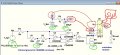
I would have shown that if it did. Out goes to the Switch output (pulse to window motor).
The other relay output is left unconnected.
Yes.
Vdd also powers the CD4093.
I don't think you want to connect the battery to either of the switch connections, you simply want to use the relay as dry contacts.
i think the schematic should be corrected to avoid the confusion, maybe something more conventional and not a sim schematic.
Again, I wouldn't use the relay to apply the battery positive to either one of the switch contacts, unless you are very sure that the switch is high side and you know for sure which terminal to connect to.
The voltage source used to represent the ignition switch might not be understood by a noobie especially since there is no switch shown in the schematic.
I can tell by the questions that the OP cannot fully understand the schematic.
The voltage source used to represent the ignition switch might not be understood by a noobie especially since there is no switch shown in the schematic.
I can tell by the questions that the OP cannot fully understand the schematic.
This circuit should also be very useful for rolling down the windows slightly to make closing doors easier. My car is pretty air tight and I need to slam the door to shut it.
My question is, what do I change to adjust the duration time? I would want to tune it to give the right amount of air gap.
Also is it possible to make the closing of the windows slightly longer duration to ensure it is always closed tight over many repetitions?
 Facebook
 Google
 GitHub
 Linkedin