Need a momentary 12V output

AnalogKid

Joined Aug 1, 2013
12,142
Why, so you can point out every little issue, while comparing it to crutschow's awesome sauce circuit?
No.

Because I want to see how many relay poles and throws, and capacitors, it takes you to trigger one 555 from both input edge directions.

Statistically, Wally uses a 555 way more than do I, while I prefer the CD4093 for miscellaneous pulse circuits even though it almost always requires an additional transistor as a load driver. Thus, the only thing awesome to me about Wally's circuit is that he finally used the right part.

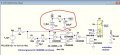
Note, you also can do the circuit with one ULN2004 and an 8-pin SIP resistor network. With all 50 V transistors, it is ultra-survivable in an automotive environment.

ak
 
Last edited:

crutschow

Joined Mar 14, 2008
38,526
the only thing awesome to me about Wally's circuit is that he finally used the right part.
Well, that's kind of you.
But I use the part that seem most appropriate for the TS's requirements.
I use a 555 when I want a:
More stable and predictable frequency or timing value,
Higher output current without an added transistor,
Better resistance to transient high voltages
as compared to the CD4093.
 

crutschow

Joined Mar 14, 2008
38,526
Yes, I can.
Okay, here's my reference parts list at Mouser.
  1. The CD4093 is here.
  2. Socket for the CD4093 is here. (14-pin socket is not available, so you can use this 16-pin socket and ignore the two unused pins).
  3. The 2N7000 MOSFET is here.
  4. The 1N4148 diode is here.
  5. The resistor can be 1/4W, 1% through-hole types here. (Order spares and some values around the shown values in chase you need to tweak the values.)
  6. The 10µF and 220µF capacitors are 16V or 20V electrolytic types here.
  7. The 12V SPST OR SPDT relays are here.
  8. Perf board is here.
Buy at least two of every thing for spares except, perhaps the relay and the Perf board if you don't want to spend that much money.

Any questions, post them here.
 

Thread Starter

yazen

Joined Jul 11, 2011
24
Okay, here's my reference parts list at Mouser.
  1. The CD4093 is here.
  2. Socket for the CD4093 is here. (14-pin socket is not available, so you can use this 16-pin socket and ignore the two unused pins).
  3. The 2N7000 MOSFET is here.
  4. The 1N4148 diode is here.
  5. The resistor can be 1/4W, 1% through-hole types here. (Order spares and some values around the shown values in chase you need to tweak the values.)
  6. The 10µF and 220µF capacitors are 16V or 20V electrolytic types here.
  7. The 12V SPST OR SPDT relays are here.
  8. Perf board is here.
Buy at least two of every thing for spares except, perhaps the relay and the Perf board if you don't want to spend that much money.

Any questions, post them here.
Perfect, thank you very much.

2N7000 MOSFET is on backorder, can I use something else instead?

Yazen
 

Thread Starter

yazen

Joined Jul 11, 2011
24
Below is the LTspice simulation of a circuit that should do what you want:
The CD4093 quad Schmitt-trigger NAND gate single package is configured as an XOR gate that gives a pulse on both the leading and trailing edge of the input.
The relay (red trace) turns on for about 1 second when the ignition switch voltage (green trace) goes both high and low.

The battery power (Vb and Vdd) must be applied to the circuit continuously so it has power when the ignition switch voltage goes low.
It takes only a very small leakage current when quiescent, so will not drain the battery.

View attachment 250866

I got the components and started working on building it. Can you please explain to me how R2, C2 and connected to the circuit?

Thank you
 

Attachments

Top