Need a circuit that can produce a one time 12V pulse when powered

Thread Starter

Michael Traynor

Joined Oct 22, 2018
7
I have an electronic door lock that I would like to install in my home.
Here's a link to the lock:

http://www.eboxlock.com/Products/1245.htm

When speaking to the manufacturer, they explained the lock needs a 12V one-time pulse to unlock it and then approx 6V to keep it unlocked (idle). I have tried several circuits but have not been able to produce these results. I plan on controlling the lock with a raspberry pi, but the initial power-on / one-time pulse needs to be able to happen without the pi's help.

I have read some things about 555 timers and "one-shot" circuits, but the examples I found are very hard to follow (it doesn't help that I'm very new to this kind of thing).

I'm looking for advice, or examples on how I can create something like this.
 

Externet

Joined Nov 29, 2005
2,645
How long that "one-time pulse" has to be ? Half a second ? And what current should be capable of delivering at 12V ?

+12VDC-------------./ .------------------||-----------------lock--------------------------gnd

The capacitor value can produce such short duration pulse. A ~10K in parallel to the capacitor is convenient.
 

Uilnaydar

Joined Jan 30, 2008
118
What about using a normally closed relay? On power up, the 12V will be applied to the lock, opening it. Then, use the Raspberry Pi to open the relay? The issue with this would be if the Pi dies, I get all your stuff as all the locks open. There are also timed relays that would alleviate me stealing all your stuffz. Relay opens after a period of time, thus force locking the contents.

With respect to using the 555 timer. You can cheat like I do and use calculators for it :)

http://www.ohmslawcalculator.com/555-monostable-calculator
 

Thread Starter

Michael Traynor

Joined Oct 22, 2018
7
Basically the first 12V pulse needs to be able to happen without the help from the pi. Then once it's been locked by the pi, I can send a 12V pulse controlled by the pi.
 
Last edited:

Thread Starter

Michael Traynor

Joined Oct 22, 2018
7
How long that "one-time pulse" has to be ? Half a second ? And what current should be capable of delivering at 12V ?

+12VDC-------------./ .------------------||-----------------lock--------------------------gnd

The capacitor value can produce such short duration pulse. A ~10K in parallel to the capacitor is convenient.
The 12V pulse needs be to be at least 500ms, and can last safely up to 10 seconds.
 

Externet

Joined Nov 29, 2005
2,645
CV = It
C x 12 = 0.8 x 1
For 1 second, 0.8 Amperes, 12 Volts

C = 0.8A x 1s /12V = 0.067 F = 67000 uF
 
Last edited:

Thread Starter

Michael Traynor

Joined Oct 22, 2018
7
Just an FYI - I at a beginner level when it comes to electrical components and circuits. I'm really just looking for some advice on which direction I should be going in.
 

Alec_t

Joined Sep 17, 2013
15,132
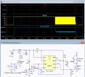
Here's a relatively simple circuit which should do what you want. At power-up 12V is applied to the lock's solenoid for ~ 0.5 sec. Thereafter, PWM (pulse width modulation produced by U1a) provides an average ~ 6V to the solenoid. A 'lock' signal from the Pi disables the PWM.
LockControl.PNG
 
Last edited:

crutschow

Joined Mar 14, 2008
38,593
Here's a 555 version of the PWM circuit.
It has a logic input to initially energize the solenoid (V_On) and turn it off.
(Not sure if you want that or the "Lock" signal that Alec's circuit has).

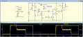
When the IN voltage goes high it momentarily applies the full 12V to the solenoid (for a time determined by R2-C3) and then reduces the voltage by the 555, oscillating as an astable multivibrator to generate a 50% duty-cycle PWM signal to the solenoid.
This reduces the average voltage to the solenoid by 50% (as you can see, the solenoid current drops by 50% after about 1/2 second).
This voltage is held as long as the IN voltage stays high.

upload_2018-10-22_10-20-18.png
 

DC_Kid

Joined Feb 25, 2008
1,242
Sounds confusing. The 12v and 6v sound like thresholds. If you apply 12v and keep it there does the device become damaged? The 6v sounds likes minimum voltage to hold the solenoid in one direction, less than 6v and the mag field is not strong enough.

Does the pi go to sleep or something?
 

Thread Starter

Michael Traynor

Joined Oct 22, 2018
7
Here's a relatively simple circuit which should do what you want. At power-up 12V is applied to the lock's solenoid for ~ 0.5 sec. Thereafter, PWM (pulse width modulation produced by U1a) provides an average ~ 6V to the solenoid. A 'lock' signal from the Arduino disables the PWM.
View attachment 162116
Would this work if I needed to pop the lock again with the Pi ?
For example:
Power connected > 12V (opens) > 6V (Idle) > Lock(0V) > 12V(to open again)
 

crutschow

Joined Mar 14, 2008
38,593
Sounds confusing. The 12v and 6v sound like thresholds. If you apply 12v and keep it there does the device become damaged?
It's a intermittent rated solenoid (see clip from data sheet below).
Likely 6V is sufficient to keep it pulled in after its energized.

upload_2018-10-22_11-55-52.png
 

DC_Kid

Joined Feb 25, 2008
1,242

Thread Starter

Michael Traynor

Joined Oct 22, 2018
7
Here's a relatively simple circuit which should do what you want. At power-up 12V is applied to the lock's solenoid for ~ 0.5 sec. Thereafter, PWM (pulse width modulation produced by U1a) provides an average ~ 6V to the solenoid. A 'lock' signal from the Pi disables the PWM.
View attachment 162116
Which NPN and PNP transistors would you recommend for this?
I currently have the 2N3904 (NPN)
and the 2N3906 (PNP).
I also have TIP120s

Thank you so much for all of your help!
 

danadak

Joined Mar 10, 2018
4,057
Good idea, but use a Adafruit Trinket 5v, it has USB interface for ease of sending the program to the unit. A much easier platform to use.
DC_Kid, I looked at its site. Is it supported for basic code like Bascom AVR supports the ATTINY ?

As an aside take a look at this $4 board, processor has lots of analog, DAC, OpAmp,
Comparator, Mixer, A/D, and digital from complex to simple gates can be wired up in
it and to/from pins. Attached is a component list. A component is an onchip resource.
The high end board which has DSP, USB, DMA.....is only $ 10. Full debug as well.
Tools and compiler free.

http://www.cypress.com/documentation/development-kitsboards/psoc-4-cy8ckit-049-4xxx-prototyping-kits

Regards, Dana.
 

Attachments

Last edited:

DC_Kid

Joined Feb 25, 2008
1,242
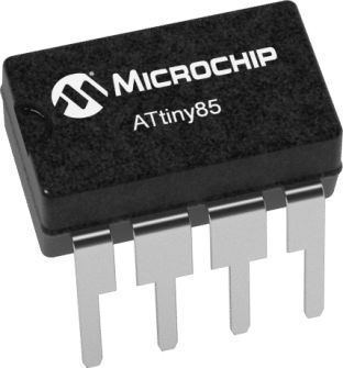
atTiny85 is fully Arduino code capable. Trinket and Trinket Pro have limited I/O and storage space. Many other IC's do more, but I found Trinket to be very ez to use for beginners, yet small enough in size, I/O, and memory, but can still do lots of things. Trinket has some limitation with SPI and debug monitoring, but one chooses a weapon wisely, etc.
 

Reloadron

Joined Jan 15, 2015
7,893
"Electric Cabinet Lock (MA1208) is a compact and all-metal lock ideal for delivery locker, cabinets, drawers and steel furniture. Surface mounting either vertically or horizontally offers easy and flexible installation. The electric cabinet lock is compatible with any existing access control system or simply controlled through a remote keypad or key switch. The cabinet lock allows mechanical override for emergency open. Electric Cabinet Lock (MA1208) is energy saving, cost efficient, robust, easy to install and suitable for one or multiple cabinet applications".

Specification
Operation Voltage 12/24VDC intermittent ±10%

Power Consumption 12V DC 800mA

Operation Mode Fail Locked

Holding Force 150KG

Maximum power on time Less than 30 second

Solenoid Rated for intermittence use

Cycle Rating More than 1,000,000 times

Mechanical Override 7mm hole

Working Temperature -20ºC ~ +60ºC

Dimensions LxWxH 72mm*56mm*13.8mm

Gross Weight 250g

Protection Class IP20

Compliance CE and RoHs certificate

Looking at the above this thing can be powered using a simple 12 VDC 1.0 Amp wall wort. They also pretty clearly state "The electric cabinet lock is compatible with any existing access control system or simply controlled through a remote keypad or key switch". With that in mind wouldn't using a Raspberry Pi be overkill? Since a simple key switch can be used I would assume any dry contact closure will unlock it? Maybe I have that wrong? If you want to program a Raspberry Pi to accept a code from a key pad I can see where a micro controller will work but it looks like all you need based on the above is a dry contact closure with the thing powered from 12 VDC? Even if you used a cypher code as several have suggested, you really don't need much beyond an inexpensive uC and a few lines of code. What exactly is the plan for using a uC and why the delay?

Ron
 
Top