Facebook
 Google
 GitHub
 Linkedin

"Electric Cabinet Lock (MA1208) is a compact and all-metal lock ideal for delivery locker, cabinets, drawers and steel furniture. Surface mounting either vertically or horizontally offers easy and flexible installation. The electric cabinet lock is compatible with any existing access control system or simply controlled through a remote keypad or key switch. The cabinet lock allows mechanical override for emergency open. Electric Cabinet Lock (MA1208) is energy saving, cost efficient, robust, easy to install and suitable for one or multiple cabinet applications".
Specification
Operation Voltage 12/24VDC intermittent ±10%
Power Consumption 12V DC 800mA
Operation Mode Fail Locked
Holding Force 150KG
Maximum power on time Less than 30 second
Solenoid Rated for intermittence use
Cycle Rating More than 1,000,000 times
Mechanical Override 7mm hole
Working Temperature -20ºC ~ +60ºC
Dimensions LxWxH 72mm*56mm*13.8mm
Gross Weight 250g
Protection Class IP20
Compliance CE and RoHs certificate
Looking at the above this thing can be powered using a simple 12 VDC 1.0 Amp wall wort. They also pretty clearly state "The electric cabinet lock is compatible with any existing access control system or simply controlled through a remote keypad or key switch". With that in mind wouldn't using a Raspberry Pi be overkill? Since a simple key switch can be used I would assume any dry contact closure will unlock it? Maybe I have that wrong? If you want to program a Raspberry Pi to accept a code from a key pad I can see where a micro controller will work but it looks like all you need based on the above is a dry contact closure with the thing powered from 12 VDC? Even if you used a cypher code as several have suggested, you really don't need much beyond an inexpensive uC and a few lines of code. What exactly is the plan for using a uC and why the delay?
Ron
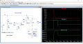
The lock is rated for intermittent use, 30 seconds max at 12V; otherwise it gets dangerously hot. It's also a fail-secure lock which means when it has no-power it's locked (needs power to unlock and to stay unlocked). In applications such as a secure entrance with a pin pad, it's a simple 12V pulse for x seconds and done. I'll be using it on a scheduled system, where the door needs to be unlocked for several hours at a time. In order for the solenoid to move it needs a 12v pulse and then it only requires a small amount of voltage (6V) for the solenoid to remain seated (unlocked). The door lock will be controlled via WiFi, and the pi zero w works well for this.