NE555 missing pulse detector

Thread Starter

farzad latifeh

Joined Oct 3, 2017
99
hi farzad,
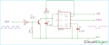
This is an example of the 555 circuit.
The components inside the dotted rectangle are only for generating the Inp pulses.
E
View attachment 336474
tanks, but I changed the subject after you asked for the schematic, the output shall be high in normal phase and when the missing pulse happened the output goes low for a second or so then the output must turn back high so the MCU boots up then again the circuit works with input pulses until the missing pulse happened again, the 1 second low output and then the high output before the MCU starts sending the square wave is an essential part of the project because the EN pin of the MCU must be high while booting up and the square wave doesn't start until the MCU fully loaded. I hope I could explain it
 

Thread Starter

farzad latifeh

Joined Oct 3, 2017
99
hi,
A drawing of the input and out signals showing the timing intervals would be helpful.
E
this circuit is very close to what I want, but it doesn't support the booting up scenario, I think of another circuit that when the missing pulse happened that circuit keeps sending similar signal instead of the MCU to the missing pulse detector for a second or so until the MCU function start then it stops until the next missing pulse is happened, I don't know if I could explain it clearly or not but the booting up phase is the main issue right now
 

Attachments

crutschow

Joined Mar 14, 2008
38,503
Okay, here's my take on a 555 circuit that, per my understanding, does (more or less) what you want:
  • The output (yellow trace) stays high for a little over 5sec when power is applied, and then goes low for 1sec if no signal is detected.
  • With no signal, it again goes low after about 1.5sec.
  • When a signal is detected (1kHz, green trace), the output goes high, and stays high as long as there is a signal.
  • It goes low again for 1sec about 2sec after the signal is lost.
Is that close?

Edit: See post #28 for revised circuit.

1732417157907.png
 
Last edited:

Thread Starter

farzad latifeh

Joined Oct 3, 2017
99
Okay, here's my take on a 555 circuit that, per my understanding, does (more or less) what you want:
  • The output (yellow trace) stays high for a little over 5sec when power is applied, and then goes low for 1sec if no signal is detected.
  • It goes low again with no signal after about 1.5sec.
  • When a signal is detected (1kHz, green trace), the output goes high, and stays high as long as there is a signal.
  • It goes low again for 1sec about 2sec after the signal is lost.
Is that close?

View attachment 336529
thanks bro, let's give it a try, I think it fulfils what I meant
 
Top