Facebook
 Google
 GitHub
 Linkedin
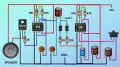
can i replace BD139 with 2SD882 in the siren circuit? there is no where i can get BD139
Attachments
-
 112.9 KB Views: 29
| Thread starter | Similar threads | Forum | Replies | Date |
|---|---|---|---|---|
|
|
NE555 timer pin5 | Digital Design | 13 | |
|
|
NE555 timer issue? | Digital Design | 15 | |
| G | Strange signal from CD4069 | Digital Design | 32 | |
| G | Trying to switch P channel MOSFET direct from NE555 - But we have failure | Analog & Mixed-Signal Design | 16 | |
| B | Sequential LED Turn Signals | PCB Layout , EDA & Simulations | 55 |