mystery setup to explain. previous user plugged batteries in a weird way . how to explain it

Thread Starter

circuityes

Joined Jun 20, 2019
39
Hello everyone.

I am having a hard time to understand how the previous user set up the 2 x 12 v batterie in this 24v weelchair and why?
is there advantage , disadvantage to set up the wires like that instead of one anderson connector per batteries each going to the chair independantly.

Also there is the wire with the 2 little balls going from neg to pos. Isn't that supposed to shortcircuit the batteries( each batterie has a 2ball wire.)
video is
manual i tried to put on archive.org : https://archive.org/details/s646se.196pages

chair is quickie 464 se

Thanks
 

panic mode

Joined Oct 10, 2011
4,971
can you not just ask previous owner what is going on? if there is only one cable going to wheelchair, batteries can only be used as 24V source if there is an adapter that combines two to one. maybe you did not get all accessories.
 

Irving

Joined Jan 30, 2016
5,108
Wheelchairs default configuration is 2 X 12v SLA in series for 24v. Often the connection between the two batteries is via a fuse or thermal breaker, typically 80 or 100A rated.

Anderson connectors would be unusual on a stock wheelchair, the manufacturers don't like spending profit on convenience, so they are almost certainly an aftermarket addition. It wasn't uncommon in the past to arrange two Anderson connectors to allow an external 'dongle' to put the batteries in parallel to charge from a car 12v high-current outlet, or to use the wheelchair to jumpstart a car. Less common now with cheap LiPo boost starters.

Unfortunately your video is so tiny I can't make out anything. Post some good large hi-res photos..

[Edit] looking at the manual, it does seem that the quickie used some form of connector in the battery wiring harness. Again, hard to tell from your video.
 
Last edited:

panic mode

Joined Oct 10, 2011
4,971
Unfortunately your video is so tiny
common for embedded videos, click on logo of the parent server to watch it there (youtube, vimeo, tiktok, whatever).

in this case click on "V" in lower right corner to watch it on vimeo. once there you can click on fullscreen.
1778531516924.png

1778531572914.png
reduced image of same thing on 4k monitor
1778531623402.png
 

MisterBill2

Joined Jan 23, 2018
27,469
A text explanation would be a good choice! The batteries would be connected IN SERIES, to supply 24 volts, for most wheel chair applications. so the connection will be from the negative of one battery to the positive of the other battery.
 

Irving

Joined Jan 30, 2016
5,108
Ok, now I've seen it full screen on a monitor, that's a standard Quickie setup. The 'two balls' items in the negative battery wires, wrapped in green plastic, are inline fuses. The harness is exactly as shown on p176 of the manual. The connection to the chair is just one 2-wire cable at 24v as is typical of all chairs I've dealt with, though most don't have a connector, just the fast-on female 'spades' onto the motor controller. The cables look to be 12awg so I'd guess this is an 80A controller and a 4mph chair. The faster 6mph chairs generally have 10awg cables for the 90 or 120A controllers.

The thin green wires, if they are wires, as they look like bits of string in some areas, may be an end-user add-on, probably for a USB charger. If so, they are dangerously unfused as far as I can see, a short would melt them and potentially start a fire without blowing the main fuses.
 

MisterBill2

Joined Jan 23, 2018
27,469
Wheelchairs default configuration is 2 X 12v SLA in series for 24v. Often the connection between the two batteries is via a fuse or thermal breaker, typically 80 or 100A rated.

Anderson connectors would be unusual on a stock wheelchair, the manufacturers don't like spending profit on convenience, so they are almost certainly an aftermarket addition. It wasn't uncommon in the past to arrange two Anderson connectors to allow an external 'dongle' to put the batteries in parallel to charge from a car 12v high-current outlet, or to use the wheelchair to jumpstart a car. Less common now with cheap LiPo boost starters.

Unfortunately your video is so tiny I can't make out anything. Post some good large hi-res photos..

[Edit] looking at the manual, it does seem that the quickie used some form of connector in the battery wiring harness. Again, hard to tell from your video.
Charging this kind of batteries in parallel is a poor choice because of the likelyhood of one battery being overcharged, and also because of the extra connections change required to go from a series connection to a parallel connection. Making that sort of change-over is inviting an accidental shorted circuit!! Doing the change in the wrong sequence will leadto a shorted circuit and cause problems.

A video explanation IS ALWAYS hard for me to follow. TEXT is much better to understand!
 

Thread Starter

circuityes

Joined Jun 20, 2019
39
can you not just ask previous owner what is going on? if there is only one cable going to wheelchair, batteries can only be used as 24V source if there is an adapter that combines two to one. maybe you did not get all accessories.
HI the past user passed away , got the chair at a trifth store.There was no possibility to contact the family of the persone. The wheelchair require 24v it would not even power on if there was only1 battery 12v if that is what you meant. The chair was working when i received it so I think all accessories are present.
 

Thread Starter

circuityes

Joined Jun 20, 2019
39
A text explanation would be a good choice! The batteries would be connected IN SERIES, to supply 24 volts, for most wheel chair applications. so the connection will be from the negative of one battery to the positive of the other battery.
Hi Mister Bill my english is already a bit struggleling, I think it would be so confusing to try to say one wire goes there etc.plus seeing the thing might give clues to people that have more xp. When you write
so the connection will be from the negative of one battery to the positive of the other battery.
do you mean in general it works like that or are you trying to explain what you see in the video if the latter i dont understand the explanation .
thanks
 

Thread Starter

circuityes

Joined Jun 20, 2019
39
. The 'two balls' items in the negative battery wires, wrapped in green plastic, are inline fuses. The harness is exactly as shown on p176 of the manual. The connection to the chair is just one 2-wire cable at 24v as is typical of all chairs I've dealt with, though most don't have a connector, just the fast-on female 'spades' onto the motor controller.

The thin green wires, if they are wires, as they look like bits of string in some areas, may be an end-user add-on, probably for a USB charg.
HI Irving the green strings are just strings I added to be able to lift the batteries more easily. You are right the drawing on p 176 corresponds to what I see on the chair atm. I also added some green painter tape at places to write on it to be able to remember how to plug this setup .

I have the same model of wheelchair and they all use anderson connector. The picture I added that is named verte is another chair I have and all the wheelchair I have had were following this pattern:eek:ne anderson connects to the chair and to the pos neg of one batteries period. The other batterie has its own connector to the chair. (so you are not confused on the verte picture you see my finger(left side) touching 2 extra cables . those are not there native , it is the way i charge the batteries on this chair not plugging them in the joystick, rather direct to the batteries to let the charger do its smart things of smart charger. So the 2 wires of my finger of verte could be erase from the picture and we would see one anderson in Y shape going to one batterie then straight in the wheelchair samething for the other . The wheelchair has 2 anderson connector by the way going to its computer.
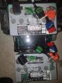
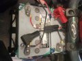
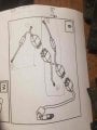
the setup of the page 176 ,we can see only use one anderson connector from the chair to computer . The other one is left unused.
=
I wonder how this setup can be considered in serie when it looks more in parallele to me since both positive terminal are linked together . Can you explain it to me?

=And why would someone use a more complex using more wires strand like the one in this post instead of the regular setup like on Verte picture? It puzzles me and I have to understand it for next step.

thanks
 

Attachments

Thread Starter

circuityes

Joined Jun 20, 2019
39
Charging this kind of batteries in parallel is a poor choice because of the likelyhood of one battery being overcharged, and also because of the extra connections change required to go from a series connection to a parallel connection. Making that sort of change-over is inviting an accidental shorted circuit!! Doing the change in the wrong sequence will leadto a shorted circuit and cause problems.

A video explanation IS ALWAYS hard for me to follow. TEXT is much better to understand!
Hi Mister Bill . Im sorry the video is not convenient for you.It felt necessity to really show what was happening. You writecharging this kind of batteries in parallel. I do not know if it charges in parallel but if the chair was functionning it means it was receiving 25 volts so it suggests it is plugged in serie. When I do look at the way wires are setup it also feels to me they are plugged in parallel but I took my multimeter once all connector plugged together and it clearly shows 24 volt when i touch one positive of one batteri and the neg of the other . Or shows zero for the other possibility. That is the behavior of batteries plugged in series from what i understand.

What makes you say that those batteries are charged in parrallel? are you certain about it ?

Thanks
 

Irving

Joined Jan 30, 2016
5,108
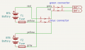
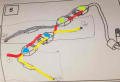
Just to be clear, here is how it is wired.....
this is exactly the same as the drawing on p176 of the manual.
1778607148860.png

1778609433205.png
 
Last edited:

Irving

Joined Jan 30, 2016
5,108
What makes you say that those batteries are charged in parrallel? are you certain about it ?
He didn't say that, I suggested that some wheelchair users have a cable assembly that allows the batteries to be fast-charged in parallel off a 12v alternator. All he said was that doing this is a bad idea - though it does work. Normal wheelchair charging is 28.8v at 4 - 6A through the standard XLR connector on the joystick. Takes 16h for a full charge!

Almost all wheelchairs I have had do not use connectors in the motor wiring - they are a constant source of problems in damp atmospheres and introduce losses we just don't need. I've never owned a Quickie.

My current chair has 100Ah custom LFP pack charged at 40A from a custom built fast charger. 10% -> 90% in under 3 hours.
 

MisterBill2

Joined Jan 23, 2018
27,469
Hi Mister Bill my english is already a bit struggleling, I think it would be so confusing to try to say one wire goes there etc.plus seeing the thing might give clues to people that have more xp. When you write
so the connection will be from the negative of one battery to the positive of the other battery.
do you mean in general it works like that or are you trying to explain what you see in the video if the latter i dont understand the explanation .
thanks
I was describing a series connection, which is the easy way that you are going to get 24 volts from two 12 volt batteries. So now I have a question: How much basic electrical circuit stuff do you actually understand?? I can give the very most basic, but that is a lot of extra if you do not need it explained.

The circuit shown in post #12 is a complicated version of exactly what I would suggest. Except: Why the extra connectors? Irving????

A 24 volt battery charger is no more complex that a 12 volt charger, it just has a different transformer.
OR you can charge one battery at a time with a 12 volt charger and never need to disconnect anything.
 

Irving

Joined Jan 30, 2016
5,108
The circuit shown in post #12 is a complicated version of exactly what I would suggest. Except: Why the extra connectors? Irving????
Because that's what's in the TS' chair and he was having difficulty reconciling that with the manual, so I drew it out and coloured the manual diagram to show they are all equivalent. I've never seen connectors in such a harness. All my chairs are directly wired without connectors.
 

Thread Starter

circuityes

Joined Jun 20, 2019
39
Because that's what's in the TS' chair and he was having difficulty reconciling that with the manual, so I drew it out and coloured the manual diagram to show they are all equivalent. I've never seen connectors in such a harness. All my chairs are directly wired without connectors.
HI First congradulation for the nice diagram and color adding.It helped me a lot . I had to meditate a bit about it but in make sense when i take it from your diagram. I imagine you had to guess which wire was going where in the anderson connector because I could not see if the red wire for example was going in the pos or neg square or the anderson connector. On your diagram. there is something missing and it is a anderson connector left unused on the wheelchair.

by saying All my chairs are directly wired without connectors do you say that all your chairs are wired like VERTE wheelchair picture or just have very long cables not using connectors?

Did you see the Verte picture where the 2 anderson connector are in use and is much simpler to understand the cables? If both setup works, Would you have any idea why the previous owner would chose the more complex wiring necessiting additionnal parts and cable?I cant understand. Maybe there is an advantage I am not aware of.

the cpu module(written vr2) from this post chair is different from the verte(qtronix). could it be that the VR2 forces to use just one anderson connector leading to the batteries?

Thanks
Im interested in lifepo4 too if only balancing and keeping balanced used cells would be easier I would probably go with a used Lfp04 cells configuration but that is another subject.
 

MisterBill2

Joined Jan 23, 2018
27,469
The difference determines how detailed the descriptions need to be. Total beginners need an explanation of series versus parallel connections, and sometimes polarity. And required wire sizes based on the current involved. That was the reason I asked. Quite a few times my explanations confuse people, so I ask.
 

MisterBill2

Joined Jan 23, 2018
27,469
What I think I see is that there are different charging arrangements possible: Charging both batteries in series at once using a 24 volt charger, or charging one 12 volt battery at a time, using a 12 volt charger, or charging both batteries at the same time, in parallel, using a single 12 volt charger and a different connection scheme. So that can be the basis for a bit of confusion.
Charging both at once in series from a 24 volt charger can be the very simplest scheme. BUT if that uses an XLR connector, I am not conviced that the current handling rating of the connector is adequate. BUTI have seen folks be very lucky so I don't argue.
 

Irving

Joined Jan 30, 2016
5,108
On your diagram. there is something missing and it is a anderson connector left unused on the wheelchair.
There's nothing I can see on the Quickie documentation that suggests another Anderson. The current Anderson goes directly to the motor controller 24v input, which is a single connector on both VR2 and Qtronix controllers (and on R-Net which isn't an option on Quickie). I can't tell you what that spare one is for.

There is a 'dual toggle' controller option, page 183, which appears to have an Anderson-style power connector, but no info how that fits in with the standard controller options.

by saying All my chairs are directly wired without connectors do you say that all your chairs are wired like VERTE wheelchair picture or just have very long cables not using connectors?
Yes, longer (and heavier, lower resistance) cables; 24v direct from batteries to motor controller (all R-Net on mine).
 
Top