My Water Irrigation System (I need help)

Thread Starter

CircuitDodo

Joined Nov 11, 2024
12
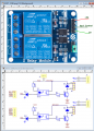
I tried doing this water irrigation system and it works but when the soil is wet, it still continues to pump water.
This is the diagram I am following:
1731353880659.png

And this is the code I used for it:

C-like:
//Tech Trends Shameer

//Smart Irrigation System


int sensor_pin= A0;

int output_value;


void setup(){

  pinMode(3, OUTPUT);

  Serial.begin(9600);

  Serial.println("Reading from the Moisture sensor…");

  delay(2000);

}


void loop()

{

  output_value= analogRead (sensor_pin);

  output_value= map (output_value,550,10,0,100);

  Serial.print("Moisture:");

  Serial.print(output_value);

  Serial.println("%");


  if (output_value<0)

  {

    delay(1000);

    digitalWrite(3, HIGH);

  }


  else

  {

    delay(1000);

    digitalWrite (3,LOW);

  }


  delay (1000);

}

Please help me in finding solutions for this. I need it urgently.
 
Last edited by a moderator:

geekoftheweek

Joined Oct 6, 2013
1,429
After skipping through the video to find the diagram and the program yours looks the same as the video.

The real question is did you hook it up correctly?

Does it show an accurate moisture reading?

What are the part numbers / links of the parts used?
 

ericgibbs

Joined Jan 29, 2010
21,390
hi CD,
What is the Serial print value when it is correctly and incorrectly feeding water.
Code line #28
output_value= analogRead (sensor_pin);

Also while running the project, disconnect pin #3 on the Arduino and check the operation of the relay by touching the end of the free wire to +5V and then 0V, the relay should operate.

If the relay switches OK on that test, then reconnect pin#3.

Then try disconnecting the Arduino A0 pin input wire, then use a test link wire to connect the A0 pin to +5V for 3 seconds and then 0V for 3 seconds, the relay should operate.

Post back here what you observe when doing these tests

E
 
Last edited:

meth

Joined May 21, 2016
298
I was going to ask the same thing that E wrote, first step is to check what result is the sensor giving and how is that in accordance to your humidity limit.
 

Thread Starter

CircuitDodo

Joined Nov 11, 2024
12
hi CD,
What is the Serial print value when it is correctly and incorrectly feeding water.
Code line #28
output_value= analogRead (sensor_pin);

Also while running the project, disconnect pin #3 on the Arduino and check the operation of the relay by touching the end of the free wire to +5V and then 0V, the relay should operate.

If the relay switches OK on that test, then reconnect pin#3.

Then try disconnecting the Arduino A0 pin input wire, then use a test link wire to connect the A0 pin to +5V for 3 seconds and then 0V for 3 seconds, the relay should operate.

Post back here what you observe when doing these tests

E
Hello, I dont exactly know python (i copied this code from someone on youtube). I will try these tests you told me but i dont know what do you mean by "use a test link wire to connect the A0 pin to +5v for 3 seconds and then 0v for 3 seconds". It would be much better if you could use a bit simpler english. I am just an 11 year old kid trying to do something for his school project.
 

Thread Starter

CircuitDodo

Joined Nov 11, 2024
12
I also have another issue, my relay module doesnt look like the exact one in the diagram.
It doesnt have the 5v pin. An image is here:
1731404163321.png
Would be great if anyone could label the pins for me
 

ericgibbs

Joined Jan 29, 2010
21,390
"use a test link wire to connect the A0 pin to +5v for 3 seconds and then 0v for 3 seconds"
hi CD,
It is just a short length of wire which you will use from the A0 pin.
Insert one end of the wire in the A0 pin socket, then hold the other end of the wire on a 5V pin, then after say 3 seconds move the wire from the 5V pin to a 0V pin.
All you are doing is simulating a 0V and 5V signal on the A0 pin.

E
 

Thread Starter

CircuitDodo

Joined Nov 11, 2024
12
hi CD,
It is just a short length of wire which you will use from the A0 pin.
Insert one end of the wire in the A0 pin socket, then hold the other end of the wire on a 5V pin, then after say 3 seconds move the wire from the 5V pin to a 0V pin.
All you are doing is simulating a 0V and 5V signal on the A0 pin.

E
Thanks, will try. It seems like you know about these things. Could you please label the relay pins for me? Image is there.
 

meth

Joined May 21, 2016
298
So what was the issue? It is always nice to share because someone else might be facing the same problem some time later, and will be searching possibly for the same solution.
 
Top