My Dual Polarity Power Supply

Thread Starter

Dataman

Joined Oct 2, 2018
28
Post a schematic if you want anyone to look at this. We don’t work from verbal descriptions
I get it,,, and I apologize. But getting a schematic without scanning my hand drawn schematic onto this thread is a challenge since Exporess PCB will not let me export any files to anything but Bit Map... so I tried to load the schematic into a program called GMP and it refused to let me do anything but print the result, So I printed the result (without any file checking - because the file check function is an Express PCB softeware function) - Anyway I printed it and then scanned it and posted the .pdf non edited version.... Well - you see where that got me (but the posted schematic shows my intent -just not a good example of proper circuit technigue),, Sorry
 

Thread Starter

Dataman

Joined Oct 2, 2018
28
Have you considered the power dissipated by the voltage regulators?

Pd = (Vin – Vout) × Iout.

For the higher voltage unit, supplying 5 volts at 6 amps:

Pd = (60 – 5) × 6 = 330 watts!
Power transitors used for Current Bypass are al mounted on heat sinks (not the dinky little ones used for the Voltage Regulatotrs TO-220 Types). The Voltage regulators only run at about 100mA so they are not a problem.
 

Thread Starter

Dataman

Joined Oct 2, 2018
28
I am using a pair of NPN/PNP Bypass Current Power transistors. I am usinf two in each path (two 12-A rated NPN and two 12A Rated PNP with 0.33R 10-Watt current balance resistors (the Power transistors and the current balance resistors are external to the PC Board).
 

Thread Starter

Dataman

Joined Oct 2, 2018
28
1.25 to 30V. You cannot get less than 1.25Volts.

How are you getting more than 1.5A?
-----edited-----
I was looking for the LM317HVS and the /LM337HVS I can't find it anymore. "obsolete" Maybe you can find them in old stock somewhere.
I am using a 2.2K 1-watt 1% resistor in series with two 1N4007 Diodes accross the +/- rails to ground to provide a negative votage refence for the regulator base voltage to get the regulators to start at a negative voltage - resulting in a working output voltage of 0-30V instead of 2Vt32V. Not elegant, but worked at 1-Amp. I consideredusing TL431s and thought about Zerner Diodes - but that did not fare well in the 1-Amps version so I simply accepted the lossey Resistor and inline diode arrangement to give me a negative reference voltage. I know it will drift with prolonged use but I have hundreds of the se LM317s LM317HVSs LM337s and LM337HVSs regulators and I simply want to a couple of build a relatively simple 0-30V/0-60V Dual Polarity Bench Supplies for testing and prototyping.
 

Thread Starter

Dataman

Joined Oct 2, 2018
28
The diodes are not big enough for 3 A or 6 A.

The high-power traces are not wide enough.

s.c.h.e.m.a.t.i.c - Paraphrasing Rear Admiral Joshua Painter,

"Engineers don't take a dump, son, without a schematic."


ak
The Bridge Rectifier Diodes are 10A10s (1000PIV and 10-Amps). For the 3-Amp and 6-Amp Power supplies that should work fine. For higher current I can scale to 20A10,,,,etc...
 

Thread Starter

Dataman

Joined Oct 2, 2018
28
And always use the component reference designators generated on the schematic for the PWB’s silkscreen.
What CAD program did you use to draw the board? Appears to be ExpressPCB… nevertheless All CAD layout software always include a schematic capture. The automatic netlist it generates is then used to draw the board, which avoids silly mistakes.
I used Express PCB that is the one provided by the PCBoard manufacturer here in the North East USA.
 

Thread Starter

Dataman

Joined Oct 2, 2018
28
Certainly a schematic drawing can be produced from thatword description of the circuit. The words description was detailed and complete, but a circuit schematic is in the common language of engineering design. AND easier to follow, as well.
The PCB layout is quite good , but quite different from traditional. I have no criticizm of the PCB, but I did not check every connection for being correct. Youstill need to verify it against the circuit schematic drawing.
Sorry - I get it... I have provided one after figuring out how to work the Manufacturer' Express PCB into thinking it was sent out for production - but the schematic was only availiable for review in a bit map version and I had to use another editing program to convert to a printable version to rescan to get a .pdf. In ediying I inadvertently changed the input and - well as you can tell in a few comments - my scanned GMP edited Version of the Bit Map used a blue refence line as a trace (Not A reference line- which I should have erased) and connected both AC inputs together - the AC common (GND) is the Voltage Regulator Common(GND) the (+) and (-) Bridge Rectifier Outputs are the (+) and (-) Voltage rails. Only the AC Line and Neutral inputs are connected to Rectifier Bridge Inputs. But I would have realized that if I had hand drawn the schematic instead of trying to print the Bit mapped Version and rescan... Dah Doooh
 

Thread Starter

Dataman

Joined Oct 2, 2018
28
If I was building a power supply, I might do this. I know there is not a negative version of this. Note this PWM does not need a heatsink.
DC to DC Buck Converter Adjustable Voltage Regulator 4-40V to 1.25-37V 2A, 3A for a short time.
View attachment 370973
Here is a 5A version with a small heatsink and a better coil.
View attachment 370974
Thanks Ron - I like those (have used a few recently) but I wnated to build two Bench Power Supplies and I already have hubdreds of the se 3-pin T0-220 regulators (even the TO-92 low power versions), And a toin of TO-3 Power transistors so building two Bench Power Supplies seemed like a somewhat doeable task (minus the Torroidial 1500VA transformers - which I will have to actually buy). The fact that all my 1/4W, 1/2W. 1/W, 2W and 3W resistors are all 1% tolerance does not mean I cannot sub them for 5% and 10% tolerance parts used in other versions. The messy part of etching my own PC boards is an issue as ny better half has declared that Ferrick Chloride is a non negotiable "no". So I am stuck using Express PCBoard as my PC Board Design Software and trust me 'It has a lot of issues - like limited parts in their part library - but hey an NPN transistor is an NPN Transistor and a PNP Transistor is a PNP Transistor. (Just have to look past the fact that both NPN and PNP Tramsistors all have the emitter pointer pointing into the Transistor in their Chematics program. And unlike the Exspress PCB Circuit Program - I cannot edit schematic parts. But this is only an incibvenience if I an trying to actually print a copy of the reference schematoic because the program automatically knows that a PNP transitor is a PNP transitors regardless of the analog schematic drawing... Maybe I will eventually actually lead modern CAD - but at my age that may or may not actually happen.
....
I apologise for my initial scree-shot of the PC Board file from Express PCB. I will not let me print sparate traces - oh wait I can - but I cannot save them anywhere.... Like my late great Grandfather always said - "You make due with what ya got - not what ya wish ya had".
 

dl324

Joined Mar 30, 2015
18,472
Now that I am retired I have more time and I want to build a couple of lab bench power supplies.
I'm also retired and consider my time better spent on things other than building power supplies.
powerSupplies.jpg
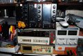
I built a jig to rearrange the output terminals on the Velleman 0-30V 3A supply on the right because having earth ground in the middle seemed brain dead to me. Then I bought the 3 Wanptek 0-30V 6A supplies. The Wanpteks costed around $40-50 each.

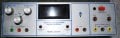
If I need a linear supply, I have a Trygon dual 0-40V 1A and an Energy Concepts 0-25V several amp supply.
20500C-PS-frontPanel.jpg

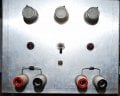
I also have several Tektronix PS-503s and a supply I made in the late 1970's.
firstPowerSupply.jpg
 

Thread Starter

Dataman

Joined Oct 2, 2018
28
I use a similar module over my bench with an X-Box power supply. This gives me fixed 5 volts, fixed 12 volts@14 amps, and adjustable 0 – 30-some volts. Details here.

View attachment 370982
I have a conveted XT Computer Power Supply where I pulled all the Wire out and wired up all the Power Outputs to Binding posts - but that is not a real lab power supply. I also have two commercial 0-30GV poser supplies that are, well commercial and not that good. So simply wanted to tackle building my own two power supplies and I figured a general generic voltage regulator PC Coard that could be used by any furure version would be a reasonable goal. Like I have already posted - I have tons of these 2-32V and 2062V 3-Pin 1-Amp linear regulators and Tons of TO-3 power tranistors - so the rest is just making it work in my old school way and trying to get modern times work in the present.
..
As you can see - my work around in posting my intentions doesn not work in this modern age because no one draws anything by hand anymore and I am not getting younger since I started hand drawing PC Board back in the mid 60s while in High school.
..
For those who have never hand drawn a svhematic, hand painted the resist onto a PC Board Blank and then actually etched a PC Board - I am sorry you missed out. I have gone from learning electronics to hand painting and etvching PC Boards, then to actually screen printing resist onto PC Boards and etching them, the tpo photo resist and developing then etching. In the 80s I transitioned to an Auto CAD Version for PC Boards but never really liked the resut. A few years back all the PC Board manufactures stopped accepting drawn PC Board designs ( which is suspect when "their" production software allows them to simply scann a hand reawn PC Board design and then produce it). Enter the lawyers - and now they cannot make my PC Board because they do not want the liability of it not working ( a risk that in reality is "my risk" bot their - so "they" want you to desing and send in a Gerber File so "they" can say it was professionally designed (???). Never mind that I have a dremmel drill press and bits to actually drill my own holes -
"Oh no - we have to have drill fie so our system can drill all the holes". So I have one choice - Etch my own boards and deal with the better half who keeps complaining about all that test equip,ent and those microscopes that I use in the shop and her belief that Ferrick Chloride is the pollutant of the world (according to her californicating wannabe friends, who believe I should be fishing while in retirement instead of waiting all that gas and jet fuel to go out for $300 hanburgers on the weekends - "But I have all these high tech Toys!" which oly seem relevant when heriPhone takes adump, or the nighbors kids Wii takes a dump and I magically make it work after 5-minutes under the microscope. Then I get the standard - "Why don't you just go fishing like all your buddies did before they died?.... ????
 

Jon Chandler

Joined Jun 12, 2008
1,645
Power transitors used for Current Bypass are al mounted on heat sinks (not the dinky little ones used for the Voltage Regulatotrs TO-220 Types). The Voltage regulators only run at about 100mA so they are not a problem.
Realize that somewhere, for the stated conditions which seem to be in your desired working range, you would be dissipating over 300 watts. Wherever you accomplish the ΔV, be it across the voltage regulators, pass tranistors, series diodes or dropping resistors, a large change in voltage × a large current results in A LOT of heat being produced. This is true for all linear voltage regulation schemes.
 

Thread Starter

Dataman

Joined Oct 2, 2018
28
How about posting a schematic instead of trying to describe the circuit with words?
As mentioned, diodes don't appear to be large enough for 6A (or 3A).
Why all of the traces that aren't multiples of 45 degrees (plus acute angles), scenic routing, and misaligned components?

Routing of the ground trace so that it just grazes pads isn't a generally accepted engineering practice.
View attachment 370959
The ground trace that is grazing the 100nF cap pad is connected to that capacitor. In the old days I put the Ground on top of the PC Board (when I started with Dual sided PC Boards - when we transitioned to multi layer I buried the Grounds and Voltage rails inside the multi layer board -but that was an 80s Auto CAD erra and I never really absorbed PC Board Multi Layer Design being a two layer PC Board kinda guy.).
 

Thread Starter

Dataman

Joined Oct 2, 2018
28
on surface LM317s make great regulators, wide input range, low quiescent current, low pin count, built in thermal protection etc. pulling Adj tab below 0V (using diodes like D5,D6) allows output to go to true zero.
but... once you factor in dissipated power, this is quickly in the realm of dreams (or nightmares). this is where switching regulators rule. if you insist on having linear regulator at the output, use switching one as pre-regulator, always producing 3-6V more than LM317 output.

btw. schematics has major mistake with dead short across AC lines. one of the AC lines need to go to midpoint between D2 and D3.
View attachment 370989
oops..... You are so right - that line was a Blue (non Rep Blue for the older graphix types) that showed up on the GMP scan and it treated it as an actual trace not a reference line that let me keep components separated by any distnce aligned. The AC Hot and Neutral are connected to the Bridge Rectifier, the (+) and (-) Voltage rail outputs come out of the Rectifier Bridge. the AC GND/OV is only tied to the GND/Common. It does not connect to the bridge rectifier because the Rectifier Bridge is just outputting (+/-) Voltage s for the power rail.
 

Thread Starter

Dataman

Joined Oct 2, 2018
28
Here is a schematic::

Hereis a schematic:::

Here is a .pdf of the schematic, Please note this is intended as a generick Powersupply... Also my Schematic Efditor does not have an LM337 (and all the Transistors are PNP - I use the JLCP OC Board Express - so I have to print and then scan everything,,,,
Hey - I apologize for the multi power supply project being posted .... I did not intend to post that other person;s project. When I scanned my schematic the wording was similar enough that I selected it when I thought I had selected "my scanned Schematic" - since there is no preview before post I did not realize I was plagurinzing annother persons work and posting it here. In all honesty - if you look at the first page of the multi output power supply project you can see who actually did that project... juts sayin....
 

Thread Starter

Dataman

Joined Oct 2, 2018
28
hi Data,
This is a clip from your PDF circuit, may help others to easily see the layout.
E
View attachment 370988
Also: Please note that the Pass transistors are connected by pins (e) (b) (c). My original intent was to only show componets mounted to this PC Board (since it is intended as a generic building block) and as far as the PC Board external components are not relevant (but are in reality considered). I only show the NPN transistor connection pins on this schematic since the Express PCBoard Schematic Software only shown all transistors as PNP. ie: all their schematic componets are drawn as PNP even the NPN transitors. So to eliminate some one pointing out that my NPN transistor is drawn as a PNP I simply put the relevant connection pins in the schematic. And Yes - I know the LM337 has the wrong pin on the diagram ( please read the note where I already pointed that out. The Express PC Schematic component library does not have an LM337 Regulator). Since "that" regulator is mounted on the PC Board I needed one in the schematic - so I stuck the LM317 and relabled it as an LM337 (I can relable but not alter pin numbering... dah.... doohhh).
 

Thread Starter

Dataman

Joined Oct 2, 2018
28
D5,6,11,12 are not temperature stable but maybe it does not matter.
I would connect C9, 18 (on the Adj pins) to Com/GND not to the diodes. Again, probably not important but a common reference for all the caps is better.
I had to re read your reply - I get it - in the non (-V) refrence version the two caps accross the potentiometers are in fact tied to common ground (because the Pot is tied to common ground). The effect seems minimal - but you are right - I should have tied C9 and C18 to common ground... Thanks for noticing that.... when I get the two proto board I will take out the dremmel and modify. I will also modify the existing Express PC Board Board File to reflect thi cahnge for the final rendition (after I get the current version proto boards back and make the change to the and copare the difference).
 

Thread Starter

Dataman

Joined Oct 2, 2018
28
And always use the component reference designators generated on the schematic for the PWB’s silkscreen.
What CAD program did you use to draw the board? Appears to be ExpressPCB… nevertheless All CAD layout software always include a schematic capture. The automatic netlist it generates is then used to draw the board, which avoids silly mistakes.
Schematic capture is not schematic print. The actual schematic is valid - problem is the validation check kept coming back as AC Ground not connected to Rectifier Bridge refernce (?? cannot figure out that point - but it went on with "If AC mains Graound is left floating it may costitute a fire/safety risk. If this is intentiomal you may dissregard this change and proceed to production). I love the PCB validate function it constanly points aout that T1 and T2 are not present on this PC Board - It stat intentional? (MY reply is Dah... Doooh ithey are external components..... My work around is always to only put the components in the Express PCBoard schematic Drawing program that are actually mounted on that PC Board. then let the Verify Function fchide at me until I make changes that maket "It Happy".
..
My Favorite is the error where it tells me I have two Pad occupying the same space - please make necessary changes befor continuing to production.... (???? Dah/Doooh - what two pads? Oh wait - I edited that one logic chip to give me a 28-Pin Normal DIP IC and combined two 14-Pin DIP ICs to get 28-Pin, then I look at "that" part and see where I overlapped the Two DIP ICs and never went back and took the overlayed pads out befoere saving the part as a 28-Pid DIP IC part in the revised part library.... I swear, when a computer is smarter that we are then it equates to letting a bunch of kindergarteners run the financial world - everythinh is o (zero) 1 (one) 0 (zer) 1 (one).. but at least it catches it when i do in fact miss and save.. But in reality - is it all that bad that two pads are actually occupying the same physical space?
...
Ooops - i am off subject... must be my ADHD ....."hey- Dounuts!"
 

Thread Starter

Dataman

Joined Oct 2, 2018
28
I'm also retired and consider my time better spent on things other than building power supplies.
View attachment 370998
I built a jig to rearrange the output terminals on the Velleman 0-30V 3A supply on the right because having earth ground in the middle seemed brain dead to me. Then I bought the 3 Wanptek 0-30V 6A supplies. The Wanpteks costed around $40-50 each.

If I need a linear supply, I have a Trygon dual 0-40V 1A and an Energy Concepts 0-25V several amp supply.
View attachment 370999

I also have several Tektronix PS-503s and a supply I made in the late 1970's.
View attachment 371000
Thanks Dennis.... I do have a lot better things to do - but at the minute I am working on this project. May or may not be better than Fishing - but I have buried 9 friends and three business partners in the last 3-years. All of them sat around fishing. Me I spend my time in Senegal Africa, Malim Africa, Mendoza, Argentina, The Bahammas and Flying around eating $300 Hanburgers and $3,000 Steaks ( $300 hanburgers if we take the Cessna Single or Twin - $3,000 Steaks if we take the Citation). That if i am not on capital Hill giving those slackers in the Congreess and senate falck about their perpetual stupidity (that was harsh wasn't it? My late grandmother always told us not to judge others inless you can walk in their shoes - ones mans stupidity could be hidden behind ignorance. That and she used to always annoy my younger brother when he complained about losing something: Sge alsways told him "Calm down, you will find it where you left it" That always out him in a huff "grandma, If I knew where it aws it wouldn't be lost" her reply" "think about that statement, then consider what I just told you"...
..
My final point is to quote the late John F Kennedy. "We are not doing it because it is easy - But because it is hard and because I want to". OK so i paraphrased and added the last tidbit,,,, His point was because it was a challemge and he was pointing out that nothing comes out of complacity, but things happen bacause people are willing to unbdertake the hard things in life and challenge the status quo....
 
Top