My Dual Polarity Power Supply

Thread Starter

Dataman

Joined Oct 2, 2018
28
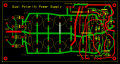
I am building a Generic Dual Polarity Power Supply PC Board. If a 48VCT Transformer is used with LM317.KM337 - you get a 0-30V Power Supply. if a 96VCT Transformer is used with an LM317HVS /LM337HVS you get 0-60 Volts. For the 0-30V I used 5 ea 820uF Caps in Parallell on each rail to give a 4,100iF Main capacitor. I put 10K resistors with 100nF caps at the Input to the 5-Cap Filter Bank and another 10K Resistor with a 100nF cap accross that resistor at the output of the multi cap main filter. I put 100nF caps accross the input pins and output pins of each Voltage Rehulator. For higher current loads I included a Positive Voltage Transistor and a Negative Voltage Power transistor so a single.or multiple power transistors can be added by simply wiring them in and providing 0.22R 10-Watt ballance resitor for each power transistor collector as it feeds power back into the combined output.
...
The goal is a 0-3Amp and 0-6Amp power Dual Rail power supply.
Note: on this PC Board Green is Bottom Copper/ Red is Top Layer Copper Foil,
 

Attachments

dl324

Joined Mar 30, 2015
18,465
For the 0-30V I used 5 ea 820uF Caps in Parallell on each rail to give a 4,100iF Main capacitor. I put 10K resistors with 100nF caps at the Input to the 5-Cap Filter Bank and another 10K Resistor with a 100nF cap accross that resistor at the output of the multi cap main filter. I put 100nF caps accross the input pins and output pins of each Voltage Rehulator. For higher current loads I included a Positive Voltage Transistor and a Negative Voltage Power transistor so a single.or multiple power transistors can be added by simply wiring them in and providing 0.22R 10-Watt ballance resitor for each power transistor collector as it feeds power back into the combined output.
How about posting a schematic instead of trying to describe the circuit with words?
The goal is a 0-3Amp and 0-6Amp power Dual Rail power supply.
As mentioned, diodes don't appear to be large enough for 6A (or 3A).
Note: on this PC Board Green is Bottom Copper/ Red is Top Layer Copper Foil,
Why all of the traces that aren't multiples of 45 degrees (plus acute angles), scenic routing, and misaligned components?

Routing of the ground trace so that it just grazes pads isn't a generally accepted engineering practice.
1788358393764.png
 

schmitt trigger

Joined Jul 12, 2010
2,229
Post a schematic if you want anyone to look at this. We don’t work from verbal descriptions
And always use the component reference designators generated on the schematic for the PWB’s silkscreen.
What CAD program did you use to draw the board? Appears to be ExpressPCB… nevertheless All CAD layout software always include a schematic capture. The automatic netlist it generates is then used to draw the board, which avoids silly mistakes.
 

MisterBill2

Joined Jan 23, 2018
28,272
Certainly a schematic drawing can be produced from that word description of the circuit. The words description was detailed and complete, but a circuit schematic is in the common language of engineering design. AND easier to follow, as well.
The PCB layout is quite good , but quite different from traditional. I have no criticizm of the PCB, but I did not check every connection for being correct. You still need to verify it against the circuit schematic drawing.
 
Last edited:

kiroma

Joined Apr 30, 2014
207
It might not be the case, but my ex-boss used to like Proteus in earlier versions because it allowed to draw the PCB before the schematics, because "it makes us gain time". Don't need to tell that this practice led to more time wasted fixing things. It would just like "take the future and bring it now and take what I'd do now and take it to the future", but instead, a mess was made, the PCB had to be remade on a newer version of Proteus, and a lot of time wasted.
 

ronsimpson

Joined Oct 7, 2019
4,811
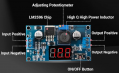
If I was building a power supply, I might do this. I know there is not a negative version of this. Note this PWM does not need a heatsink.
DC to DC Buck Converter Adjustable Voltage Regulator 4-40V to 1.25-37V 2A, 3A for a short time.
1788386022711.png
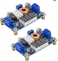
Here is a 5A version with a small heatsink and a better coil.
1788386290061.png
 

Thread Starter

Dataman

Joined Oct 2, 2018
28
The diodes are not big enough for 3 A or 6 A.

The high-power traces are not wide enough.

s.c.h.e.m.a.t.i.c - Paraphrasing Rear Admiral Joshua Painter,

"Engineers don't take a dump, son, without a schematic."


ak
The rectifier diodes are 10A10, for higher Current 20A10 or even 30A10 (although I personally woulduse bolt on Stud rectifiers or a Full wave Brifge Rectifier with Cripon Connections (but prefer Screws at 25Amps or above).
 

Jon Chandler

Joined Jun 12, 2008
1,644
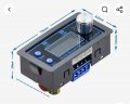
An easy option would be a buck-boost module like the one pictured here, about six bucks on AliExpress. Supply it with 5 – 30 VDC and you have a regulated, current limited supply that will provide 0.5 – 30 volts out at up to 3 amps/30 watts. It displays voltage, current, wattage, energy used, etc.

To make a bi-polar supply, use 2 modules, each with a separate power supply. Laptop power bricks make good supplies.

Screenshot_20260902_200358_AliExpress.jpg
 

AnalogKid

Joined Aug 1, 2013
12,272
The rectifier diodes are 10A10, for higher Current 20A10 or even 30A10
Without a schematic, there is no way for us to know that.

The diode decal on the board layout is incorrect (too small) for those components. Also, the hole diameters are too small.

Please post separate images of the two routing layers; just the pads and traces, no decals or reference designators.

ak
 

Thread Starter

Dataman

Joined Oct 2, 2018
28
I am building a Generic Dual Polarity Power Supply PC Board. If a 48VCT Transformer is used with LM317.KM337 - you get a 0-30V Power Supply. if a 96VCT Transformer is used with an LM317HVS /LM337HVS you get 0-60 Volts. For the 0-30V I used 5 ea 820uF Caps in Parallell on each rail to give a 4,100iF Main capacitor. I put 10K resistors with 100nF caps at the Input to the 5-Cap Filter Bank and another 10K Resistor with a 100nF cap accross that resistor at the output of the multi cap main filter. I put 100nF caps accross the input pins and output pins of each Voltage Rehulator. For higher current loads I included a Positive Voltage Transistor and a Negative Voltage Power transistor so a single.or multiple power transistors can be added by simply wiring them in and providing 0.22R 10-Watt ballance resitor for each power transistor collector as it feeds power back into the combined output.
...
The goal is a 0-3Amp and 0-6Amp power Dual Rail power supply.
Note: on this PC Board Green is Bottom Copper/ Red is Top Layer Copper Foil,
Here is a schematic::
I am building a Generic Dual Polarity Power Supply PC Board. If a 48VCT Transformer is used with LM317.KM337 - you get a 0-30V Power Supply. if a 96VCT Transformer is used with an LM317HVS /LM337HVS you get 0-60 Volts. For the 0-30V I used 5 ea 820uF Caps in Parallell on each rail to give a 4,100iF Main capacitor. I put 10K resistors with 100nF caps at the Input to the 5-Cap Filter Bank and another 10K Resistor with a 100nF cap accross that resistor at the output of the multi cap main filter. I put 100nF caps accross the input pins and output pins of each Voltage Rehulator. For higher current loads I included a Positive Voltage Transistor and a Negative Voltage Power transistor so a single.or multiple power transistors can be added by simply wiring them in and providing 0.22R 10-Watt ballance resitor for each power transistor collector as it feeds power back into the combined output.
...
The goal is a 0-3Amp and 0-6Amp power Dual Rail power supply.
Note: on this PC Board Green is Bottom Copper/ Red is Top Layer Copper Foil,
Hereis a schematic:::
I am building a Generic Dual Polarity Power Supply PC Board. If a 48VCT Transformer is used with LM317.KM337 - you get a 0-30V Power Supply. if a 96VCT Transformer is used with an LM317HVS /LM337HVS you get 0-60 Volts. For the 0-30V I used 5 ea 820uF Caps in Parallell on each rail to give a 4,100iF Main capacitor. I put 10K resistors with 100nF caps at the Input to the 5-Cap Filter Bank and another 10K Resistor with a 100nF cap accross that resistor at the output of the multi cap main filter. I put 100nF caps accross the input pins and output pins of each Voltage Rehulator. For higher current loads I included a Positive Voltage Transistor and a Negative Voltage Power transistor so a single.or multiple power transistors can be added by simply wiring them in and providing 0.22R 10-Watt ballance resitor for each power transistor collector as it feeds power back into the combined output.
...
The goal is a 0-3Amp and 0-6Amp power Dual Rail power supply.
Note: on this PC Board Green is Bottom Copper/ Red is Top Layer Copper Foil,
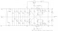
Here is a .pdf of the schematic, Please note this is intended as a generick Powersupply... Also my Schematic Efditor does not have an LM337 (and all the Transistors are PNP - I use the JLCP OC Board Express - so I have to print and then scan everything,,,,
 

Attachments

panic mode

Joined Oct 10, 2011
5,250
on surface LM317s make great regulators, wide input range, low quiescent current, low pin count, built in thermal protection etc. pulling Adj tab below 0V (using diodes like D5,D6) allows output to go to true zero.
but... once you factor in dissipated power, this is quickly in the realm of dreams (or nightmares). this is where switching regulators rule. if you insist on having linear regulator at the output, use switching one as pre-regulator, always producing 3-6V more than LM317 output.

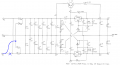
btw. schematics has major mistake with dead short across AC lines. one of the AC lines need to go to midpoint between D2 and D3.
1788441468917.png
 
Last edited:

ronsimpson

Joined Oct 7, 2019
4,811
D5,6,11,12 are not temperature stable but maybe it does not matter.
I would connect C9, 18 (on the Adj pins) to Com/GND not to the diodes. Again, probably not important but a common reference for all the caps is better.
 

AnalogKid

Joined Aug 1, 2013
12,272
R1-R2 and R6-R7 are in direct parallel and can be reduced.

With a 48 V transformer, the peak voltage out of the filter caps is around 32 V, so the 317 is very close to dropping out of regulation with a 30 V output and no load. As the ripple voltage increases with load, some ripple will appear at the output.

Also, the voltage reference inside the 317 has a nearly perfect zero temperature coefficient. Not so for the two bias diodes (per output). Depending on where they are located, this can add both a warm-up and a temperature-dependent drift to the output regulation. There is another thread where the circuit uses an additional LM317 to create the negative bias with no drift.

ak
 

Thread Starter

Dataman

Joined Oct 2, 2018
28
on surface LM317s make great regulators, wide input range, low quiescent current, low pin count, built in thermal protection etc. pulling Adj tab below 0V (using diodes like D5,D6) allows output to go to true zero.
but... once you factor in dissipated power, this is quickly in the realm of dreams (or nightmares). this is where switching regulators rule. if you insist on having linear regulator at the output, use switching one as pre-regulator, always producing 3-6V more than LM317 output.

btw. schematics has major mistake with dead short across AC lines. one of the AC lines need to go to midpoint between D2 and D3.
View attachment 370989
oops... My bad (rookie mistake) in the Express PCB Schematic generator you have to draw a line accross common input paths to keep everything symetrical (fancy term for lined up). I simply forgot to remove it and the editor simply connected
How about posting a schematic instead of trying to describe the circuit with words?
As mentioned, diodes don't appear to be large enough for 6A (or 3A).
Why all of the traces that aren't multiples of 45 degrees (plus acute angles), scenic routing, and misaligned components?

Routing of the ground trace so that it just grazes pads isn't a generally accepted engineering practice.
View attachment 370959
Thanks - I am trying to get the express PCB software to do rounded angles but as a novice it is chalenging. I had three PCB boards already made of a stripped down version of this layout - and they worked with only 1Amp rated current. Now I am trying to ramp up to 3A and 6Amp versions. Uwsing AI (and I use this term lightly) the prototype PC Board had a shorted Input (thanks to the comment post that pointed out the shorted AC Inputs). I have a gerber based auto CAD program that I am trying to transition to and the learning curve is dragging me down. I have used Express PCB for multiple audio projects and I personally wanted to build my a couple of Dual Polaroty LAB Bench PS (one for 0-30V and one for 0-60V). This is my first stab and frankly had I hand drawn the schematic most of the current errors would not be there . (a few years back all of the PCB manufacturers quit accepting hand drawn PC Board designs so Express PCB became my go-to solution - aparently not a good one for Power PCBoards). Now that I am retired I have more time and I want to build a couple of lab bench power supplies. The errors in this drwing are the result of my my work around the non-functional "snap to grid" function that I used in the 1990 version of Auto CAD light. I miss the snap to grid function of Auto CAD but it is what it is.
 
Top