My amplifier doesn't work very well [2N3904][collector feedback bias][capacitor mic]

Thread Starter

booboo

Joined Apr 25, 2015
168
Hi everybody
I'm working on this circuit:


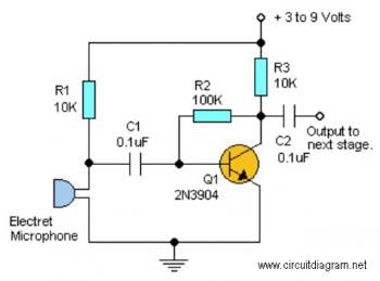
I have wired it up but the output is oscillating between 20mv-3mv. the supply is 9v. I don't have anything about my microphone. I have picked it up from the headset of my PC. should I cascade the output to two or maybe three stage? I'm newbie to using BJT as amplifire. How can I calculate the gain of this amplifire?
 

Thread Starter

booboo

Joined Apr 25, 2015
168
I changed R2 to 1MegOhm but nothing happened. a picture of my circuit:


The pots in the picture is R1, R2 and R3.
 

Bordodynov

Joined May 20, 2015
3,430
Your amplifier has a very low input impedance. This is due to the negative feedback (resistor R2 = 100k Rin ~ 100k / (A +1) || Ztrans ~ 0.5kOhm. Can optimize the amount of R2, and it is possible to add RC -filter.
Mic.png
 

DickCappels

Joined Aug 21, 2008
10,661
(Some text removed for clarity.)

I have wired it up but the output is oscillating between 20mv-3mv.

(Some text removed for clarity.)
How can I calculate the gain of this amplifire?
Is the 20mv -3mv oscillation the problem, or are you just worried about the gain?

This is a transimpedance amplifier (with low loop gain), as such the output P-P voltage will try to be the P-P current from the JFET in the mic times the value of R2.
 

Thread Starter

booboo

Joined Apr 25, 2015
168
Is the 20mv -3mv oscillation the problem, or are you just worried about the gain?

This is a transimpedance amplifier (with low loop gain), as such the output P-P voltage will try to be the P-P current from the JFET in the mic times the value of R2.
I'm just worried about the gain.
 

Thread Starter

booboo

Joined Apr 25, 2015
168
I have measured the output of headset jack of my PC and it was 3.3v.
Your amplifier has a very low input impedance. This is due to the negative feedback (resistor R2 = 100k Rin ~ 100k / (A +1) || Ztrans ~ 0.5kOhm. Can optimize the amount of R2, and it is possible to add RC -filter.
View attachment 88331
Thanks but 70mv isn't enough. I want to get the output between 0v-3v3. any seggestion?
 

AnalogKid

Joined Aug 1, 2013
12,060
At such low base and collector currents, your transistor probably will not have a gain of 200. But even if it did, with 5 mV coming from the mic that's only 1 V output voltage, and it would have distortion caused by the almost complete lack of feedback. For a circuit gain of 660 (57 dB) you will need two stages in series, each with a gain of 26, to get the output you want with reasonable distortion.

Open question - This one-transistor preamp circuit has been around for decades, but I've never seen it done with a Darlington transistor. Anyone know why?

ak
 

Jony130

Joined Feb 17, 2009
5,593
Open question - This one-transistor preamp circuit has been around for decades, but I've never seen it done with a Darlington transistor. Anyone know why?

ak
Maybe because the voltage gain for a Darlington CE amplifier will be two times smaller than a single transistor CE amplifier.
 
Last edited:

DickCappels

Joined Aug 21, 2008
10,661
Jony130 has a point.
Its been done with Darlingtons for many decades, in audio output stages, for example.

By the way, (back to the single transistor gain stage) because of the dependence of the emitter resistance on current and because the current through the emitter is approximately equal to the current through the collector load, the maximum gain of a stage like will be less than the voltage across the collector load x 38. Therefore you will need multiple gain stages as AnalogKid indicated.

You won't get a 3.3 volt peak-to-peak output voltage with a 3.3 volt power supply and that topology; how much do you really need?
 

Thread Starter

booboo

Joined Apr 25, 2015
168
Thanks guys for reply

At such low base and collector currents, your transistor probably will not have a gain of 200. But even if it did, with 5 mV coming from the mic that's only 1 V output voltage, and it would have distortion caused by the almost complete lack of feedback. For a circuit gain of 660 (57 dB) you will need two stages in series, each with a gain of 26, to get the output you want with reasonable distortion.
ak
If you were me, how would you do it? What type of biasing? which one exactly?
...
You won't get a 3.3 volt peak-to-peak output voltage with a 3.3 volt power supply and that topology; how much do you really need?
Let's assume my supply is 9v. a 3.3v peak-to-peak output is what I need. no matter how many transistor or what type of biasing. I have also these transistors in stock:

2N3906,2N3904,BC548,BC557,BC338,BC327,BC337,BF199

my goal is just learning.;)
 

Jony130

Joined Feb 17, 2009
5,593
In the diagram that I posted (13) a NPN transistor (T1 on the diagram) is wrongly labeled.
T1 is a NPN so 2N3904,BC548,BC338,BC337 can be used. Also notice that 2N3904 ( and PNP version 2N3906) has a different pin out then the European transistors BCxxx.
As T2 (PNP) you can use thus 2N3906,BC557,BC327. Don't forgot about
different pin out.
 

RichardO

Joined May 4, 2013
2,270
To get rid of oscillation and power line induced hum you need to shorten the wires in your circuit. Also, don't forget to add power supply bypassing.
 

#12

Joined Nov 30, 2010
18,224
The top thread in Completed Projects right now contains the circuit in post #1.
You might examine how that person did this circuit.
 

Thread Starter

booboo

Joined Apr 25, 2015
168
Try this circuit
View attachment 88339

You can change gain by changing R5 value. Gain ≈ R4/R5
Ok and Thanks
I will try this tomorrow. I was busy today.
Two question:
What type of biasing is used for T1 and T2? I think it's common-collector for T2. right? What about T1?
What are the usage of R4 and R7 and R8?
You can shorted two input pins of microphone, normally it will be 0V at the output.
What's the point? I cannot get it. could you more explain, please?
To get rid of oscillation and power line induced hum you need to shorten the wires in your circuit. Also, don't forget to add power supply bypassing.
shorten? you mean I should use breadboard? I have to solder them? Is this what you are saying?
The top thread in Completed Projects right now contains the circuit in post #1.
You might examine how that person did this circuit.
This:
http://forum.allaboutcircuits.com/threads/audio-preamplifier-project.113313/
He/she hasn't said anything about its Mic.
 

RichardO

Joined May 4, 2013
2,270
shorten? you mean I should use breadboard? I have to solder them? Is this what you are saying?
The picture of your circuit shows many long insulated wires. These wires act as antennas and pick up stray signals from power line wiring creating hum. In addition, the long wires can couple to each other causing feedback and oscillation.

I would recommend using short wires that are flat against the solderless bread board. Also, the resistors and capacitors should have the leads cut short so that they are against the SBB when installed. I always use the leads cut from the resistors and capacitors for my jumpers. Using un-insulated wires encourages using short wires.
 
Top