CLASS D Amplifier Power stage doesn't work well

Thread Starter

Jose Espigares Perez

Joined Jun 25, 2017
21
Hi Everybody,

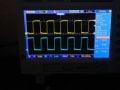
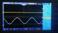
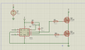
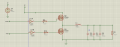
I have the next attatched power stage, for my Class D amplifier. The main problem is that I can't get more than 6 volts and 500mA in the output .

I would like to get unless 1.5A or 2A. ¿Any idea about what is happening? ¿Why the mosfets do not amplify enough?

The PWM and notPWM are signals switching between 0V and 12V.

Thanks a lot in advance!
 

Attachments

crutschow

Joined Mar 14, 2008
38,337
You need a bootstrap driver to fully turn on the top MOSFET.
That MOSFET is operating as a source follower and thus its output is more than one Vgs threshold drop below the 12V gate drive.
It needs a gate voltage at least 10v above the drain supply voltage to turn on as a switch.
You can use a bootstrap driver such as the IR2110 for that purpose.

Do the two gate-drive signals have a turn-on delay between them so there is sufficient signal non-overlap to avoid shoot-through current at the switching time?
 

Thread Starter

Jose Espigares Perez

Joined Jun 25, 2017
21
I have tried to substitute the IR2110 for one TC4426. Because IR2110 has a lot of problems. Also, I have a delay time between each signal.

Which P channel mosfet can I use?

Thanks
 

Thread Starter

Jose Espigares Perez

Joined Jun 25, 2017
21
I bought my mosfets in a local store, I prefer to use TC4426 because is cheaper and easier to use. But I dont know why the mosfets are not working well.
 

Alec_t

Joined Sep 17, 2013
15,109
But I dont know why the mosfets are not working well.
Crutschow told you in post #3.
The IRF540 has a Vgs(thr) voltage which can be as high as 4V, i.e. you might need at least 4V even to start conduction. However, to switch the FET on fully needs a Vgs of 10V (as per the datasheet). That means if Vcc is 12V and Q2 gate is 12V (TC4426 output high), then Q2 source can't go above 12V-10V=2V while still maintaining full conduction.
 

Thread Starter

Jose Espigares Perez

Joined Jun 25, 2017
21
Crutschow told you in post #3.
The IRF540 has a Vgs(thr) voltage which can be as high as 4V, i.e. you might need at least 4V even to start conduction. However, to switch the FET on fully needs a Vgs of 10V (as per the datasheet). That means if Vcc is 12V and Q2 gate is 12V (TC4426 output high), then Q2 source can't go above 12V-10V=2V while still maintaining full conduction.
If I would have 30V MOSFET's power supply , I shouldnt have problems then. ¿Have I understood ok?
 

crutschow

Joined Mar 14, 2008
38,337
If I would have 30V MOSFET's power supply , I shouldnt have problems then. ¿Have I understood ok?
Don''t think so.
It's the gate-source voltage of the top transistor required to fully turn it on that's the problem, not the drain voltage.
Just increasing the supply voltage won't help that.

To restate, the source voltage is alway at least the MOSFET Vgs threshold voltage below the gate voltage.
So to turn the MOSFET fully on with minimum drain-source ON voltage, you need to have the gate voltage at least 10V above the drain supply voltage.
Why is that hard for you to understand?
 

Thread Starter

Jose Espigares Perez

Joined Jun 25, 2017
21
I'm so sorry, but I'm not a native english speaker so, please Understand me.

OK, so I need 10V more in the gate than in the Drain. How can I get it?

Because my driver works between 4.5V and 18V Vcc, so it's very difficult to get 10V more.

Any solution or idea?

Thank you very much for your replies MR. crutschow.

Bye.
 

Thread Starter

Jose Espigares Perez

Joined Jun 25, 2017
21
Ok,

I have made a circuit with the IR2110 but I have doubts about where some pins are connected, and how to calculate my bootstrap cap.

First: ¿Is this design OK?¿Is the Bootstrap CAP OK?

Secondly: In the datasheet there are two signals more than proteus design.

- VSS that I think it should be connected to GND ¿Right?
- VDD that I have seen in some forums that they connect it to +5V, but I have to connect it to +12V for its correct working. ¿What is it correct voltage?

Thank you very much.
 

Attachments

crutschow

Joined Mar 14, 2008
38,337
Is this design OK?¿Is the Bootstrap CAP OK?
It's fine.
You could likely go with 0.1μF if you like.
VSS that I think it should be connected to GND ¿Right?
- VDD that I have seen in some forums that they connect it to +5V, but I have to connect it to +12V for its correct working. ¿What is it correct voltage?
Yes, VSS goes to common

VDD should be connected to your logic level voltage, typically 5V.

VC is the for the gate bootstrap voltage so you want that to be about 12V to 15V, not 40V.

Note that for the bootstrap to work, VS needs to be also connected to the junction of the two MOSFET's source and drain.

(Just a nit, but ¿ marks are not used in normal English. Just use ? at the end of the question.) ;)
 
Top