CLASS D Amplifier Power stage doesn't work well

Thread Starter

Jose Espigares Perez

Joined Jun 25, 2017
21
It's fine.

"VC is the for the gate bootstrap voltage so you want that to be about 12V to 15V, not 40V."
Yes, sorry I have forgotten to delete VCC=40V, but in the High side's Mosfet I think that it's OK. Because, If I need more output power I will increase this High Side DRAIN voltage.

"(Just a nit, but ¿ marks are not used in normal English. Just use ? at the end of the question.) ;)
Haha, yes I'm sorry sometimes I forget that I'm talking in English ! My mind is still thinking in Spanish.

Thanks!
 

crutschow

Joined Mar 14, 2008
38,689
I have forgotten to delete VCC=40V, but in the High side's Mosfet I think that it's OK. Because, If I need more output power I will increase this High Side DRAIN voltage.
No, it's not okay.
That will blow the top transistor as the maximum Vgs is generally 20v.
The bootstrap works by having the gate voltage rise with the source voltage (bootstrapped) but at a voltage of Vcc above the source voltage to keep the top transistor ON as the source voltage rises
The source voltage then becomes essentially equal to the drain voltage when the switching is done with the gate voltage Vcc above the source.

I suggest you read up on bootstrapped circuits so you understand how they work.

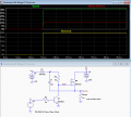
Below is a simulation that may help:
Initially with the MOSFET off, the source is at 0V and C1 charges to about 11V through D1
When the MOSFET starts to turn on, the source voltage rises which raises the bottom voltage of C1.
Since a capacitor can't change voltage without charge flow, the top voltage of C1 rises with the bottom (source) voltage.
The gate voltage thus rises with the capacitor (and source) voltage through R2 and, at the end of the rise, it's 11V above the source voltage.
At this point the source voltage is essentially equal to the drain voltage.
This makes the gate-source voltage, V(Gate,Source) about 11V, as desired to keep the MOSFET fully turned ON.

upload_2017-7-3_21-12-42.png
 
Last edited:

Thread Starter

Jose Espigares Perez

Joined Jun 25, 2017
21
Wow, thank you very much for your simulation example.

But I still have one question about my logic supply voltage, because you said to me that tipically is 5V. But, my HIN and LIN inputs have a signal which comes from a comparator switching between 0 Volts and 12 Volts. So, I need 12 volts in Vdd Pin, it's ok?

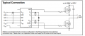
Also, I have seen that in IOR 2110's datasheet talks about Vb and in its tipical connection, drain High side mosfet goes to +500V. Why I cannot connect my High side drain voltage to +40V then?
 

Attachments

crutschow

Joined Mar 14, 2008
38,689
But, my HIN and LIN inputs have a signal which comes from a comparator switching between 0 Volts and 12 Volts. So, I need 12 volts in Vdd Pin, it's ok?
Yes, if your logic levels are 12V then Vdd should also be 12V.
Also, I have seen that in IOR 2110's datasheet talks about Vb and in its tipical connection, drain High side mosfet goes to +500V. Why I cannot connect my High side drain voltage to +40V then?
As I stated in post #22, that will apply 40V to Vgs which will blow most MOSFET gates.
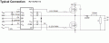
Besides, Vcc (which goes to the diode for the bootstrap) is limited to 25V as shown here from the data sheet (please read it):
upload_2017-7-3_22-26-31.png
 
Last edited:

crutschow

Joined Mar 14, 2008
38,689
The IR2110 incorporates level-shifting and the output totem-pole is floating, so if Vdd=12V and Vdrain (not Vdd) is 40V then Vs will pull up to ~40V and Vg will go to Vs+12V = 52V. Note that Vgs is still 12V.
Yes, looking back over the posts I think we may be referring to two different voltages.
I'm talking about Vcc (Vc) which is the Vgs ON voltage applied to both MOSFETs.

But the high side drain voltage can cerainly go up to over 500V, depending upon the MOSFET's ratings.

Sorry about the confusion. :oops:
 
Last edited:

Thread Starter

Jose Espigares Perez

Joined Jun 25, 2017
21
Hi everybody!

Today I have changed my circuit and it seems that now it's working...

But, I have one DC Power supply for High side drain voltage. When I set the DC Power supply to 15V everything is OK, I have one AC signal around 8VAC. But If I try to increase this voltage (High side drain voltage) to 30VDC, the signal only increases its offset. I dont know, why the amplitude doesnt increase. I have made a video for a better understanding.

What do you think about that?


Thread Starter

Jose Espigares Perez

Joined Jun 25, 2017
21
Sorry, my fault. There was one floating ground. Right now, power stage is working correctly.
Finally, I want to design a filter for an electric guitar. I think that its range is between 1Hz and 15kHz.

Now, I have a filter with 15uF Cap and 330uH inductor. And there are a lot of noise and the signal doesn't sound very clear, in fact it's very distorsioned.

I have changed the inductor for 150uH and the signal is cleaner than the previous one, but I want to be sure that filter design is fine, to buy the correct components.

Could you help me with filter design?

Thank you very much.
 

crutschow

Joined Mar 14, 2008
38,689
Not surprising it sounds a little strange.
How did you arrive at those values?
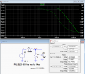
That circuit is an underdamped resonant circuit with a large resonant peak at about 1.5kHz and a sharp rolloff above that, as seen here in an LTspice simulation.
upload_2017-7-7_0-23-55.png

Try the values below.
They give a -3dB rolloff at 15kHz and a -36dB rolloff at your 140kHz PWM frequency with a flat response in the audio band.
upload_2017-7-7_0-59-26.png
 

Thread Starter

Jose Espigares Perez

Joined Jun 25, 2017
21
I have changed the old filter, for a new one, with your specifications, but It's still very distortioned. I don't know how to reduce it, any suggestion?

Thanks a lot in advance.
 

Thread Starter

Jose Espigares Perez

Joined Jun 25, 2017
21
Yes the preamp was overdriving the modulator.

Finally, I have one question about the filter. Could you teach me, how did you get this LC values with my PWM frequency?

I would like to learn this filter equations.

Thanks!
 

crutschow

Joined Mar 14, 2008
38,689
Could you teach me, how did you get this LC values with my PWM frequency?

I would like to learn this filter equations.
Sorry, I just tweaked the values in the simulation until I got the desired AC response from the filter.
It basically involves selecting values so the damping factor (Q) of the circuit is such that there is a smooth rolloff with no peaking.
I'm not big on doing the math so perhaps someone else can help you with that. :)
 
Top