I started looking at the following: XY-WJ01, XY-WM01 and ZK-KTD2
Basically all very similar in features and price.
I chose the XY-WM01 because it uses MOS instead of a relay and will probably be more reliable since no moving parts.
The XY-WM01 also does not seem to handle AC, but I do not mind that.
Apart from that there some additional programs in some of them, but I only need the most basic program so I do not care.
Also I need low-trigger and all of them seem to support that.
You can find all of them around $8 on Amazon but I chose the linked supplier because they can deliver in 2 days to me for a higher price.
No, not from that. “Button”, for example can be pulling the input low. But, worst case, you can add a single transistor and a couple of passive components to invert the signal—so wait until you get it before panicking.
You are engaged in premature optimization—the bane of good engineering design.
No, not from that. “Button”, for example can be pulling the input low. But, worst case, you can add a single transistor and a couple of passive components to invert the signal—so wait until you get it before panicking.
You are engaged in premature optimization—the bane of good engineering design.
@Ya’akov Here is the manual I was sent for the XY-WM01
Tell me if I am engaging in 'premature optimization' again
3>.MOS output. It uses MOS to control the output, so it can output the voltage value, which is equal to
the input voltage value within DC 6V-30V 10A. Built-in optocoupler isolator to enhance anti-interference
ability.
I hope that is not saying what I think it is saying.
ie. when the output is ON, does it pass power from the 2 input pins to the 2 output pins? I hope not. All I want is for the 2 output pins to connect to each other.
@Ya’akov Here is the manual I was sent for the XY-WM01
Tell me if I am engaging in 'premature optimization' again
I hope that is not saying what I think it is saying.
ie. when the output is ON, does it pass power from the 2 input pins to the 2 output pins? I hope not. All I want is for the 2 output pins to connect to each other.
Unfortunately, it is exactly that. The supply voltage is connected to the output. You’ll have to add a relay to make that work. The original one would have been fine because it was just a relay closure and even though this one says “relay” in the description, it doesn’t have one.
Q1: If I keep the trigger button pressed, will the selected program run only once? or will the program run again and again until I stop pressing the trigger?
A: It should not be possible to keep pressing the button, the trigger button just detects the rising or falling edge, that is, the signal level from low to high or from high to low conversion moment.
Q2: Does it support Low Trigger Signal: DC 0.0V~0.2V ?
A: Yes, support low level triggering, as well as high level triggering. it support Low Trigger Signal: DC 0.0V~0.2V.
Q3: Are the outputs ALWAYS independent of the inputs? When it gets triggered I do not want power on the output from the input ; I only want the output pins to connect to each other.
A: This timer relay output is always independent of the input. Because it is a relay output, the relay is internally switched completely independently and has no connection to the original power supply.
Specification and parameter description
Specification:
Operating voltage: DC 5.0V ~ 30V
Trigger type: Button/PNP/NPN/High/Low Level Signal
High Trigger Signal: DC 3.0 V ~ 24 V. Output type: Relay switching output (no voltage output).
Load (max): DC 30V 10A or AC 250V 10A.
Working current: 50 mA
Quiet current: 20 mA
working temperature range: -40°C ~ 85°C.
Working moisture range: 5% - 95%
relative humidity.
Module size: 79 x 43 x 26 mm
Features:
16 types of working modes, high/low level or PNP/NPN signal trigger, 2200 W, 10 A relay driver, optocoupler insulation protection, supports the UART communication function, support parameter memory function, support the forced stop function
Parameter description:
Operation: Delay time for switching on; CL: Delay time for switching off; LOP: Number of cycles. The range is between 1 and 999 times. ----" means unlimited loop.CLL: Minimum value of random delay time range. The adjustment range is between 0.0 and 99.9 seconds. This CLL parameter is used for the P15 working mode. CLH: Maximum value of random delay time range. The adjustment range is 0.0 to 99.9 seconds. This CLH parameter is used for P15 working mode. CLH value is greater than CLL value.
Crap!
How about this one? ZK-KTD2 Specification and parameter description
Specification:
Operating voltage: DC 5.0V ~ 30V
Trigger type: Button/PNP/NPN/High/Low Level Signal
High Trigger Signal: DC 3.0 V ~ 24 V. Output type: Relay switching output (no voltage output).
Load (max): DC 30V 10A or AC 250V 10A.
Working current: 50 mA
Quiet current: 20 mA
working temperature range: -40°C ~ 85°C.
Working moisture range: 5% - 95%
relative humidity.
Module size: 79 x 43 x 26 mm
Features:
16 types of working modes, high/low level or PNP/NPN signal trigger, 2200 W, 10 A relay driver, optocoupler insulation protection, supports the UART communication function, support parameter memory function, support the forced stop function
Parameter description:
Operation: Delay time for switching on; CL: Delay time for switching off; LOP: Number of cycles. The range is between 1 and 999 times. ----" means unlimited loop.CLL: Minimum value of random delay time range. The adjustment range is between 0.0 and 99.9 seconds. This CLL parameter is used for the P15 working mode. CLH: Maximum value of random delay time range. The adjustment range is 0.0 to 99.9 seconds. This CLH parameter is used for P15 working mode. CLH value is greater than CLL value.
OK I got the XY-WJ01 from amazon here. Coming next Wednesday.
(Even though I am sure the ZK-KTD2 would be just as good. The XY-WJ01 does have a nicer screen though.)
Dear Ya’akov, the device (XY-WJ01 from amazon here) arrived last week and proceeded to install it last Friday.
It works perfectly! Thanks for your guidance in this project.
To mute the BMW CCC head unit (N38a) I had to:
A. Program the XY-WJ01
Working Mode: PO ( Relay will keep ON for time OP after get trigger signal and then relay OFF; The input signal is invalid if get trigger signal again during delay time OP.)
Turn On time (OP): 0.1s
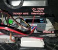
B. Connect a trigger wire to the 'LOW' pin inside the box. The trigger wire was then connected to my triggering device.
(To bench-test, I powered the device and I connected my 12V phone charger to the outputs. I then touched the LOW wire onto the negative power terminal. This caused the charger to start charging. For testing I had OP at 10s.)
(I was not provided with a 3-pin header plug with the relay, so I used a header plug from a Noctua computer fan which I modified slightly to fit. I also used the Noctua fan male&female connector to connect the trigger wire to the LOW header)
C. I soldered 2 wires to the Volume Knob (encoder) of the BMW CCC head-unit and connected them to the 'Relay Output' of the XY-WJ01. When the XY-WJ01 was triggered, the 2 wires were connected for 0.1s. This was enough to mute the head-unit.
NOTE:
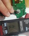
In order to reach the encoder to solder the wire, you must first remove the volume knob. This took the strength of both my hands pulling on the knob at the same time! As long as you are pulling straight and not sideways, it should be ok.
The facia is held in place by only 2 plastic clips (bottom side of the facia). You only have to push them a couple of milimeters with a screwdriver to release one side of the face at a time. (youtube vids exist)
There is a small narrow ribbon cable that has to be disconected now.
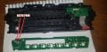
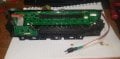
Once the facia is out, then you remove the screws holding the board. Also disconnect the wider ribbon cable so the board can come out.
Turn the board over and solder your wire on the encoder's top side which has only 2 pins (bottom side has 3).
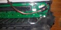
Fasten the cable so that pulling on it will not hurt their soldered connections. Used a rubber cable holder/guide.
I soldered spade connecors at the other ends for easy connect/disconnect to my extension cable going to the XY-WJ01.
I also later wrapped the cable with fabric tape for zero noise.
Installation:
To install in the car, I made use of the space on the driver side footwell.
On the underside of this panel there is ample room. You will find some acoustic dampening pads.
I glued velcro (soft/loop) every few centimeters using fabric glue and left to dry for a day.
I glued velcro (hard/hook) on the underside of the device and placed it where I saw fit.
This allows for much flexibility in placement of any component.
Just be careful when removing a component - hold down the base fabric before lifting your device up, otherwise you may end up lifting half the pad along with your device.
Dear Ya’akov, the device (XY-WJ01 from amazon here) arrived last week and proceeded to install it last Friday.
It works perfectly! Thanks for your guidance in this project.
Thanks for the complete write up. It’s very helpful for future reference—a way of paying forward and more than sufficient compensation for any help I provided.
Don’t hesitate to come back with any new projects, or even just to hang out and help others when you have some information.
 Facebook
 Google
 GitHub
 Linkedin

")