Help with Mute circuit

Thread Starter

maurouhle

Joined Dec 30, 2016
24
My Dell Altec Lansing Dolby 5.1 speaker system caught on fire. Blown electrolytic capacitor inside woofer box. I removed all boards and power supply. I then built a new supply and used a smaller audio system based on a TPA3116D2 TI circuit. It all works well but there is a loud pop sound at power on or off.
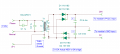
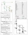
On TI's website for the module, there is a link for a sample power supply circuit (AN-1849) which includes a mute circuit as shown on the attachments.

So, I know by my tests that the mute circuit for this device needs a high voltage (+VCC) to mute, contrary to the sample circuit. Also, the VCC for the module should not exceed 30V and yet the sample power supply shown not only is a dual supply but, the voltage is too high, 80V

That said, how can I mute all channels during power on and off? I am afraid to damage the speakers. Thank you! Mauro

TPA3116D2 data sheet, product information and support | TI.com
 

Attachments

LowQCab

Joined Nov 6, 2012
5,101
The Circuit shown provides a ~+2-Volt Mute-Signal by using an LED as a Zener-Diode of sorts,
while at the same time, providing a Visual-Indicator that the Amp is muted.

The "Pop" is not likely to cause any damage,
it's mostly just an annoyance.
.
.
.
 

Thread Starter

maurouhle

Joined Dec 30, 2016
24
The Circuit shown provides a ~+2-Volt Mute-Signal by using an LED as a Zener-Diode of sorts,
while at the same time, providing a Visual-Indicator that the Amp is muted.

The "Pop" is not likely to cause any damage,
it's mostly just an annoyance.
.
.
.
Thank you for replying, so, you are confirming that it will not work on my amplifier module, right? My module mutes when I apply VCC (+26V)
 

LowQCab

Joined Nov 6, 2012
5,101
The Mute-Pin probably operates at ANY positive Voltage greater than maybe ~0.8-Volts.
Just don't exceed the VCC-Voltage to the Chip.
.
.
.
 

sghioto

Joined Dec 31, 2017
8,633
Thank you for replying, so, you are confirming that it will not work on my amplifier module, right? My module mutes when I apply VCC (+26V)
It will work with the correct selection of component values however its operation relies on using high value filter caps (20,000uf ) in the power supply to function properly. You mentioned building a new supply, can you post the schematic?
 

Thread Starter

maurouhle

Joined Dec 30, 2016
24
It will work with the correct selection of component values however its operation relies on using high value filter caps (20,000uf ) in the power supply to function properly. You mentioned building a new supply, can you post the schematic?
I can draw it, it has a new Toroidal transformer, dual 9V sec, centers connected to ground, full wave rectification with a capacitor of 4400uF on each + and - sides to ground. At full audio power there is vey little ripple.
 

sghioto

Joined Dec 31, 2017
8,633
It will mute. When removed, it will work. The sample circuit from TI has the mute pins connected to ground via a resistor.
This should provide a delayed mute when first turned ON. Curious to see if this works.
How are you switching power to the amp?
Yes I would like to see a drawing of the schematic. Is this a dual polarity supply?
1688159979334.png
 
Last edited:

Thread Starter

maurouhle

Joined Dec 30, 2016
24
This should provide a delayed mute when first turned ON. Curious to see if this works.
How are you switching power to the amp?
Yes I would like to see a drawing of the schematic. Is this a dual polarity supply?
View attachment 297414
It worked fine. I recorded the ambient sound when clicking on and off without, with your circuit and with your circuit and music The power off pop is lower with music and can leave with it. The tall spikes at each sample is the power switch noise. Thanks!
 

Attachments

sghioto

Joined Dec 31, 2017
8,633
I have another circuit that's designed to remove the pop on power off as well as on if you want to try.
Why do you have the center connection of the secondary windings connected to the transformer shield?
Is VF1 the ground conductor in 110 volt power cable?
 
Last edited:

Thread Starter

maurouhle

Joined Dec 30, 2016
24
I have another circuit that's designed to remove the pop on power off as well as on if you want to try.
Why do you have the center connection of the secondary windings connected to the transformer shield?
Is VF1 the ground conductor in 110 volt power cable?
Sure, I can try your circuit. The sample circuit from TI would eliminate the pop at power on and off per diagrams on my original message. I thought the central wires should be connected somewhere other than just the caps, I can disconnect and test for noise. And yes, VF1 is the power ground. The original Dell / Altec did not have a ground but my Toroidal has a shielding, for this reason I run the ground wire also,
 

sghioto

Joined Dec 31, 2017
8,633
You can leave the shield connected to the power ground but disconnect from the transformer secondary. With the secondary connected to the ground of the power cable it is no longer fully isolated from the primary as the neutral and ground wires in the power cable are normally connected together in the breaker panel.
The other issue is that you have two 4400uf caps in series which actually reduces the total capacitance to half or 2200uf.
Connecting the junction of the secondaries with the caps is fine if you are building a dual polarity supply of plus and minus 13
volts. The circuit I will post later to eliminate the pop on power Off depends on a high amount of filter capacitance to keep the amplifier On for a short time when the main power switch is turned OFF. This was explained in the AN-1849 publication.
I would suggest connecting the two 4400uf caps in parallel for this purpose. Make sure they are rated at least 35 volts.
Revised power supply schematic:
1688263250549.png
 

sghioto

Joined Dec 31, 2017
8,633
Mute goes high on power up during time delay. When power shuts off mute goes high again when the power supply discharges to appx 24 volts.
R2 value is configured for Vcc of 26 volts.
 
Top