Mr, I would like to use a 555 timer to alternate two blinking LED's,

Thread Starter

stspringer

Joined Oct 1, 2019
81
Yes they were, where you soldered all those red wires together on the switch. From that junction you only needed one wire to the breadboard.
Ah yes, so many different moves I made, I forget what I was doing. I now have it working, I did initially use a lever wire nut, but now I am connected direct to the breadboard and everything is good so far. I am so glad you did not run out of patience with me and helped me so much. I learned an awful lot with you at my side.

I am still getting intermittent blink issues, but for now I will blame it on my breadboard.

I will solder it on a proto board and see what happens. I will let you know what happens.

Thank you again for all your help
 

Thread Starter

stspringer

Joined Oct 1, 2019
81
sghioto, guess what the issue was with the high beams acting weird? I was using a 12v wall wart for my testing and not my bench power supply in the basement of my house. Well when I put the breadboard on the bench power supply everything is working 100%, I am super happy! This will help you too, letting guys like me not use a wall wart when building a circuit.

Must have been the wall wart couldn't handle the, almost 2 amps ,of the high beams.

I never use a wall wart, but this time I didn't feel like working in a cold basement, so I did it at my desk upstairs with the 12v wall wart. Lesson learned.

Thank you again Sir, you are the best! I will probably be needing your assistance in the future, if it's ok with you.
 

Thread Starter

stspringer

Joined Oct 1, 2019
81
Hello sghioto,
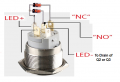
Interesting find. How do I go about giving power to the LED indicator on the push button switch when the low beams are on?

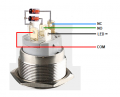
I have the switch indicator light blinking in sequence with the high beams, but when the high beams are off, there is no power to the LED indicator light. If I feed it power, the high beams kick on because of the jumper wire feeding the no wire.

Thanks for any help
 

Thread Starter

stspringer

Joined Oct 1, 2019
81
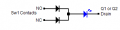
Just need to wire two diodes to the switch as shown below.
View attachment 294071
Ok thanks, but just wondering, how is one supposed to do all this to the switch and have the switch in a practical setup to connect the switch and reconnect the switch with say a male female connector?

Let's say you gave this circuit to a friend, how would he ever, hook up the push button switch to his motorcycle, or car?
 

sghioto

Joined Dec 31, 2017
8,737
Realistically you can mount the diodes directly to the switch because they are small. This would only need 4 conductors to complete the M/F connector.
Or you could install the diodes on the circuit board along with the rest of the components and use a 5 wire M/F connector.
1683927328060.png
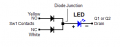
In the schematic the 2 diodes are represented by D4 and D5.
1683929917352.png
 
Last edited:

Thread Starter

stspringer

Joined Oct 1, 2019
81
Realistically you can mount the diodes directly to the switch because they are small. This would only need 4 conductors to completed the M/F connector.
Or you could install the diodes on the circuit board along with the rest of the components and use a 5 wire M/F connector.
View attachment 294091
In the schematic the 2 diodes are represented by D4 and D5.
View attachment 294092
Nice, you make life so much easier :) Thanks again
 

Thread Starter

stspringer

Joined Oct 1, 2019
81
Realistically you can mount the diodes directly to the switch because they are small. This would only need 4 conductors to complete the M/F connector.
Or you could install the diodes on the circuit board along with the rest of the components and use a 5 wire M/F connector.
View attachment 294091
In the schematic the 2 diodes are represented by D4 and D5.
View attachment 294093
Hello sghioto,
I didn't mount the diodes in the switch, I tried on the breadboard first, and they got hot and smoked. I must be unclear on the hookup on the breadboard, thanks
 

Thread Starter

stspringer

Joined Oct 1, 2019
81
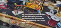
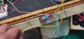
I know this is a very messy shot, sorry for that. I connected to the Positive LED indicator from the switch, the two diodes legs, cathode side facing into the lever wire nut, then connected a wire from the wire nut to the positive 12v rail on the breadboard. I then took the other leg of one diode and connected it to the "NC" white wire on the breadboard which is feeding the low beam LED modules and the amps went high on my bench power supply, things got hot.
 

Attachments

sghioto

Joined Dec 31, 2017
8,737
then connected a wire from the wire nut to the positive 12v rail on the breadboard.
This is where you went wrong!
There is no connection from the junction of the diode cathodes to 12 volts. Is the LED in the switch still working?
This is how it should be connected. Is this clear?
1684082774913.png
 

Thread Starter

stspringer

Joined Oct 1, 2019
81
This is where you went wrong!
There is no connection from the junction of the diode cathodes to 12 volts. Is the LED in the switch still working?
This is how it should be connected. Is this clear?
View attachment 294191
Yes, the LED in the switch is still working. So I put the diode in series with the NO yellow wire, and the same in series with the NC white wire and the ground wire of the switch to the drain of either Q1 or Q2 correct?
 

Thread Starter

stspringer

Joined Oct 1, 2019
81
Ok, I still had the jumper wire connected in my switch, my bad.

I disconnected the jumper wire and to make things easier, on myself, I took the two diodes and made an opening in the + led indicator wire and soldered the two diode cathode leads to the led indicator + wire, then I made an opening in the white NC wire and the yellow NO wire and I soldered the other leg of each diode to each respective wire.

Nothing gets hot all is working, but the LED indicator doesn't light on low beam, just the high beam LED indicator lights and it blinks in sequence with the LED modules as it should. I am connected to the drain with the switch ground wire.
Am I nuts or what?
 

Attachments

Last edited:

Thread Starter

stspringer

Joined Oct 1, 2019
81
You won't believe this! Changed out diode low beam led indicator came on and high beams work, BUT when on low beam switch not pressed, one of the LED module's blinks on and off, and the low beam led indicator stays lit and solid. Crazy! I changed out the transistor 3904 no go, changed out mosfet no go. Unplug the led + indicator from the 12v rail and the LED moule stops blinking, and the switch LED indicator stays lit, but then of course no high beams when I press the switch button. Have to go now doing Mother's Day now. :)
 
Last edited:
Top