How to identify bad component in timer?

Thread Starter

Failer

Joined Jul 11, 2009
20
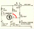
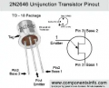
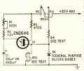
I have a power sequencer, built about 60 years ago, with the last stage not operating. I haven't fully drawn out the entire schematic but it seems pretty straightforward, its a timer built around a 2N2646 UJT, which energizes a latching relay after the cap charges. It is very similar to the circuit shown in Radio-Electronics June 1968, pg 39, Fig. 11. This is the diagram I have been working with. There are some minor differences, but it's conceptually the same.


The entire thing is original, carbon comps, old caps, you name it. I could just replace all the caps, resistors, and the UJT, but I am trying this as a learning experience. But I need guidance on testing. I'm not too familiar with troubleshooting of this variety and I don't know where to start. I though the place to start would be to see what, if any, voltage develops across the cap. Would this be the place to start?
 

MrChips

Joined Oct 2, 2009
35,110
The first thing to do is describe the symptoms or behavior. We can only guess.

Let's say, for example:
"When power is applied, nothing happens. The relay remains in the NC position."

If this is the case, the first test is to jumper across base1 and base2 of Q1, (not the emitter). (Or the bottom leg of R3 to the buttom leg of R4, as drawn in the schematics).

1789164940828.png

The relay should energize.
This checks R3, RY1, N.C. contacts and power.

If it stays energize, it checks N.O. contacts and R4.


1789164496989.png
 

Thread Starter

Failer

Joined Jul 11, 2009
20
I'm asking since, like I said this is a learning experience for me. Is shorting around a transistor like that generally a usual method? I'd be concerned about cooking something. Is it OK here because it's switching and not amplifying?

Funny thing... I figured it shortly after I posted. The NC contact on the relay had extremely high resistance, basically wasn't powering the circuit at all. Cleaned the contacts and it's back to operational. I guess for a non-sealed relay with a date code of 1966, that lifespan is not too shabby.

Since I was waiting on a response, I was poking around in the way that I'm used to as an HVAC tech, and noticed that the relay did latch when pushed on, so my original assumption was that something was dead in the timer circuit. I guess I was part right... dead because it wasn't getting any power.

How about this, I don't expect an answer for this from anybody, but it never hurts to ask, right?

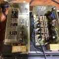
This sequencer is some kind of used surplus stuff that my dad bought in the 80's. There are several, with dates of 1966 through 1969. The stages do not time off of each other with a fixed time, they all power on together, and each stage simply has a longer delay time than the preceding one.

The construction and the cad-plated metal frame makes me think that this was possibly military or probably industrial/technical, like old H-P products or something. They were stamped with a variety of manufacturers throughout that time... AEMCO, MidTex (I know these are the same company) and one, "EOS" , which I'm not familiar with. All have the same part number, 11S82, which proved to be useless in various Internet searches. Just for the heck of it, I emailed TE, who now owns what used to be the Midtex line, and they just gave me some useless answer that sounded like AI (even though he said it wasn't) which just repeated the information that I provided to begin with. At least they could have just said they didn't know.

This seems like a long shot, but is there anyone here who might recognize this thing, and what it's original use might have been?

I like it as a power sequencer (for my stereo) because it has a distinct personality. Because whatever it was built for (and also possibly due to aged resistors) the time delay between stages isn't quite consistent. It's click.click.....click..click.
Anyway, thought I'd throw that question out here.
IMG_7467.jpg
 
Last edited:

MrChips

Joined Oct 2, 2009
35,110
To answer your question, shorting any component is not a good thing.
Let me explain.

1) I don’t usually go about replacing components to start.
The usual procedure is to know the history, symptom and current behaviour.

2) We do the sensory inputs, look, smell, touch. Look for the usual suspects, bad fuse, burnt resistor, bulging or leaking capacitors, burnt PCB tracks.

3) Having access to the circuit schematics is a huge advantage. Without it, you have to reverse engineer the circuit.

4) Once you have the circuit you can do some serious trouble shooting. This is your road map if you know how to use it. This requires a sound understanding of how circuits work.

Thus, no, shorting any component is a bad idea unless you understand how the circuit works. I can see from reading the schematics that the specific instructions I gave you was a safe thing to do.

In retrospect, knowing what was wrong, a simple test with a voltmeter would have indicated no voltage from R3 to ground.

5) A good starting point for trouble shooting electronics is to check for voltage.
 

Thread Starter

Failer

Joined Jul 11, 2009
20
I get you, thanks. In my experience with HVAC controls, it's not uncommon for me to have to go poking around with a meter through a mess of wires and components without having a schematic available. That's how I found the issue, so it's not like I have no experience, but it's more like, I don't generally get down below the component level. Troubleshooting a specific problem on PCB components is something that I usually only do on my own time, we don't do that at work.
So, I am working with some hybrid knowledge here. I thank you for your help. I have many years worth of basic electronics knowledge that I need refreshed, and more hands-on time applied.
 

MrChips

Joined Oct 2, 2009
35,110
Troubleshooting a specific problem on PCB components is something that I usually only do on my own time, we don't do that at work.
And that's the problem. It costs too much to pay technicians to do repairs at the component level. They are told to replace the board and then have to charge minimum $300 for the board alone plus labor. They are not trained to trouble shoot at the component level.
 

Thread Starter

Failer

Joined Jul 11, 2009
20
I agree, but I think there's liability sides to it as well. I could probably replace blown parts in a VFD without any issues, but with stuff that size and that expensive, things like technician training and warranty status, and potential multi-million dollar problems, it's frankly better that we stick to the board level. Replacement logic control board for a York liquid cooled VFD is about $15K. $300 boards might be a residential amount, I work on million-dollar chillers for customers that require a $5 million dollar insurance bond on file just for me to set foot on site. When I went to night school for AC repair years ago, I just assumed that we would be learning the type of repairs that you are thinking of, turns out most HVAC troubleshooting is done with a DMM to find the bad part, replace and you're on your way.

I have often wondered what my job would have been like 50 years ago when parts were generally more expensive than labor, because that's certainly not where we are today. And the frugal, technical minded side of me doesn't really like throwing away things that I could probably fix. A lot of the older techs (and some of the better new ones) feel the same way, that's why we play around with stuff like this on our own time.
 
Top