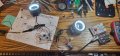
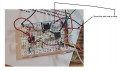
Yes but the battery plus lead only connects to the green common on the switch. Does not connect to the breadboard.
That means move the red battery lead to a empty slot on the breadboard and connect the green wire from the switch to the same location so that the two wires only connected to each other.
Yes but the battery plus lead only connects to the green common on the switch. Does not connect to the breadboard.
That means move the red battery lead to a empty slot on the breadboard and connect the green wire from the switch to the same location so that the two wires only connected to each other.
Hello sghioto,
Ok, I wired the switch as per your diagram and the low beams are working steady on, full 12v, all good.But the high beams are not working. If
Hello sghioto,
Ok, I wired the switch as per your diagram and the low beams are working steady on, full 12v, all good. But the high beams are not working. I don't get it. The NO is connected to the collector of Q1 right?
Check the resistors and make sure there isn't a short. It appears to me that R1 (100K ) might be touching that 100K resistor from pin 6 to 7 on the 555.
Holly smokes I just must have touched something on the circuit and now the blinking is alternate! Maybe some components were touching LOL I think two resistors were touching, so far I am a happy camper! Thanks to you Sir
Wait maybe spoke too soon things are acting up on the blinking
Might be this crapy breadboard too, seems like the one led is cutting out then back in and brighter than the other led Nuts!
Where they are connected now. The two high beam wires and NO on the switch are connected together along with the 555 and Q1 circuits as in the schematic. Just follow the wiring on the breadboard.
Where they are connected now. The two high beam wires and NO on the switch are connected together along with the 555 and Q1 circuits as in the schematic. Just follow the wiring on the breadboard.
They were not connected in the pic i uploaded to you, just the low beams were connected. What I did which is probably incorrect is I used a lever wire nut with the no wire and the two high beam wires, and it worked but then got wacky. So to connect them directly to the bread board do I connect them all to q1 collector? Sorry if I am screwed up

 Facebook
 Google
 GitHub
 Linkedin