Hello sghioto,
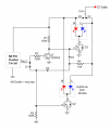
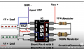
I followed your schematic, I think I got it right, and the low beams come on at full 12v, but when I remove the low beam wires and plug in the high beam wires, the LED's blink on and off, but they do NOT alternate, they both blink at the same time and the voltage never gets to 12v it's like 3 to 6 v.
No. Works just like it should.
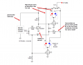
Both circuits I posted worked fine using either the 2N3906 or the 2N3904.
I prefer the last refinement using the 2N3904.
No. Works just like it should.
Both circuits I posted worked fine using either the 2N3906 or the 2N3904.
I prefer the last refinement using the 2N3904.
What do you see different between the two transistors 2N3906 or the 2N3904 ? I will try again. Thanks
sghioto, I am unclear on some of the connections on your latest schematic, I am not well versed in schematics, can you give me some layman explanation to my confusion? thanks
The transistors are the opposite of each other like the difference between a P and N channel mosfet.
Give me the link to the LED modules and the switch and I'll redraw the circuit and the wiring.
The transistors are the opposite of each other like the difference between a P and N channel mosfet.
Give me the link to the LED modules and the switch and I'll redraw the circuit and the wiring.

 Facebook
 Google
 GitHub
 Linkedin