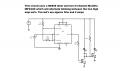
Mr, I would like to use a 555 timer to alternate two blinking LED's,

Thread Starter

stspringer

Joined Oct 1, 2019
81
Hello All,
The circuit works as expected with just the high beams blinking, then I added a 5 conductor push button locking switch.

New development. The LED's have dual beams, high and low. I put on a 5 conductor switch which has a built in LED indicator light, to turn on the high beams and the low beams, when the high beams are off. The switch has a "NC" wire "white" and a "NO" wire "yellow". The yellow wire turns on the high beams and blinks them as expected. The white wir is the "NC" and turns on the low beams when the high beams are off.

When I turn off the high beams that blink the high beams, the NC wire will light the low beams which are steady on no blinking, which is what I want.

Problem:
The low beams are only getting like 3 or 4 volts, there is a voltage drop because the ground wire of the LED lights are connected to the drain of the mosfets. The N channel mosfets are ground side switched.

Should I use P channel mosfets? Or are there other options to get the full 12v to the low beam LED's when I turn off the high beam blinking sequence.

Thanks for any help
 
Last edited:
sghioto

Joined Dec 31, 2017
8,729
Problem:
The low beams are only getting like 3 or 4 volts, there is a voltage drop because the ground wire of the LED lights are connected to the drain of the mosfets.
Don't understand that. If the dual beam LEDs share a common ground then it seems both high and low would blink when the switch is in either position.
Can you draw a schematic of how you have it wired?
 

Thread Starter

stspringer

Joined Oct 1, 2019
81
Don't understand that. If the dual beam LEDs share a common ground then it seems both high and low would blink when the switch is in either position.
Can you draw a schematic of how you have it wired?
Hello Sghioto,

Yes, the high and low beams share a common ground, the ground of the led's are connected to the drain of each mosfet , the switch has 5 conductors, green is common, red is for the led indicator in the switch, black is ground, yellow is "NO" white is "NC"

I have it set up so that the, led indicator, on the button switch is always lit, when the button is not pressed the "NC" has power from the common wire, and feeds the low beam conductors, on the led "load" lights, the high amp LEDs, now when I press, the latched switch button down, the "NO" button is now closed and power from the common goes to the yellow wire to the circuit board positive rail, and the high beam leds blink via the drain on the mosfets.

The low beam LEDs do come on when I turn off the blinking high beam LEDs, but they are very dim only getting 8 volts, dropping 4 volts approximately.

So the problem is I have a bad ground, high resistance on the ground side when the low beams are active and the high beams are off. The push button locking switch with the LED indicator acts just like a relay with pins 30, 87, and 87a. pin 30 would be common 87a is "NC", 87 is "NO" which sends the power from pin 30 common to the load.

I hope this is clear, I will try and get you a schematic with the switch in the schematic>

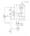
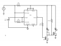
I am not used to schematic drawing, but here is my schematic without the switch, I think it is good,I used free web based circuit diagram to create it.circuit (1).png
 
Last edited:

sghioto

Joined Dec 31, 2017
8,729
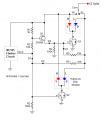
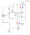
In order to isolate the the high and low beams the circuit will require a complete overhaul.
I haven't tested this circuit but believe it will work from what you have described.
The Red LED in the module represents the high beam, Blue the low.
1683376358769.png
 
Last edited:

Thread Starter

stspringer

Joined Oct 1, 2019
81
Yes it did.
Wow, I hope I can follow this schematic, it looks pretty deep for my level of electronic skill. I am amazed at how you can visualize this circuit to make it work, there are so many variables from what I can understand. Thank you very much for you much needed support. Did you actually build this circuit or did you use a simulator?
 
Last edited:

ElectricSpidey

Joined Dec 2, 2017
3,347
When I look at that schematic, I see the high beams blinking when the relay is in one position and the low beams blinking when the relay is in the other position.

I see no steady state on either beam. But instead alternating between sets.

In other words, the two red LEDs alternate, or the two blue LEDs alternate.

But I'm probably wrong due to being a stupid electron current user.

EDIT:

Ok I see my mistake now.
 
Last edited:
Top