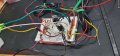
here is the latest pics I did two new diodes soldered on the switch and the low beam led indicator comes on but the 1 led module blinks on and off the low beam. The high beams work as they should and the led indicator blinks in sequence with them.
Bottom line, one LED module blinks on and off on low beam, and the low beam LED indicator is steady on
I just found my error. I forgot the wire spliced off of the NO wire to the breadboard, I was using the LED + indicator on the breadboard positive rail. I feel so dumb, I must have been tired and not thinking straight from all the troubleshooting and testing. I am a happy camper finally! Thill the next adventure LOL Thanks again sir, you are the best!
That's insurance. You don't want the on/off state of a MOSFET to be "undetermined", or dependent on only the capacitive charge on the gate. Those resistors are called pull-down resistors because in absence of a voltage applied to turn the gate ON, they discharge the gate capacitance and ensure the MOSFET gets turned off in fairly short order.
In many circuits the gate voltage "should" be controlled by ... something, but it's good form to assume that something won't always be either on or off. The resistor makes sure the gate voltage shuts off conduction D-to-S so that a dangerous current cannot flow through the MOSFET in that case.
That's insurance. You don't want the on/off state of a MOSFET to be "undetermined", or dependent on only the capacitive charge on the gate. Those resistors are called pull-down resistors because in absence of a voltage applied to turn the gate ON, they discharge the gate capacitance and ensure the MOSFET gets turned off in fairly short order.
In many circuits the gate voltage "should" be controlled by ... something, but it's good form to assume that something won't always be either on or off. The resistor makes sure the gate voltage shuts off conduction D-to-S so that a dangerous current cannot flow through the MOSFET in that case.
I'm sorry, I didn't look carefully at your drawing and thought you had included the pull-down resistors that the TS was asking about. I didn't realize he was asking about something not shown. My bad.
I just built this circuit on a proto board all soldered and all is working,
Then I just saw this post after I had installed the 10k resistors across the gate and the source of the mosfets, and the LED module on Q3 stopped working, but Q2 was still working, so I removed the 10K resistors from Q3 and Q2.
sghioto,
I know a diode is a check valve that allows current to flow in just one direction, but could you explain what is happening with D1, D2, and D3, in newbie terms so I can wrap my head around it. Thanks
Also known as steering diodes or isolation diodes.
I'll start by saying without D2 and D3 the high and low beam LED on Q2 would never come on. Without D1 the low beam on Q2 would not come on as well.
In this application the diodes perform the important function of isolation because you have three interactive circuits.
Similar situation with D4 and D5.
The three diode D1-D3 are only required because of the common negative of the LED lights.
A diode does allow current in only one direction but it also must be biased correctly for that to happen. The voltage on the anode side of the diode must be higher then the cathode side for current to flow. D1 is a prime example. When the switch is in the low beam mode the voltage on the anode of D1 which is connected to pin3 of the 555 is less then 1 volt while the cathode is at appx 10 volts. Because of this D1 is like an open switch which isolates Q2 from the 555 which otherwise would pull the gate of Q2 too low preventing it from turning on in the low beam mode.
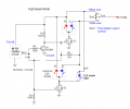
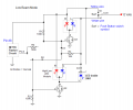
The schematics below represent the effective circuits when in the high and low beam modes. Meaning the missing components
are essentially not there.
High beam mode:
Also known as steering diodes or isolation diodes.
I'll start by saying without D2 and D3 the high and low beam LED on Q2 would never come on. Without D1 the low beam on Q2 would not come on as well.
In this application the diodes perform the important function of isolation because you have three interactive circuits.
Similar situation with D4 and D5.
The three diode D1-D3 are only required because of the common negative of the LED lights.
A diode does allow current in only one direction but it also must be biased correctly for that to happen. The voltage on the anode side of the diode must be higher then the cathode side for current to flow. D1 is a prime example. When the switch is in the low beam mode the voltage on the anode of D1 which is connected to pin3 of the 555 is less then 1 volt while the cathode is at appx 10 volts. Because of this D1 is like an open switch which isolates Q2 from the 555 which otherwise would pull the gate of Q2 too low preventing it from turning on in the low beam mode.
The schematics below represent the effective circuits when in the high and low beam modes. Meaning the missing components
are essentially not there.
High beam mode: View attachment 294456

 Facebook
 Google
 GitHub
 Linkedin