Facebook
 Google
 GitHub
 Linkedin
Audioguru again
- Joined Oct 21, 2019
- 6,826
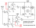
Your redrawn circuit will not work:
1) The upper P-channel Mosfets will never turn off.
2) The lower N-channel Mosfets will barely turn on.
3) The gates of all the Mosfets will burn out with almost 24V on them.
I cannot read the part numbers of the Mosfets so they might need a Vgs of 10v to turn on. Your emitter-followers will have an output of 0.3V to 4.3V.
Attachments
-
 60.5 KB Views: 8