I changed the sim to use a 2N3906 (PNP) for the bottom transistor and it works much better.
I don't like the fact that the top MOSFET has no DC path for the gate. It works OK in the sim but would probably not in a real circuit.
I too changed it to pnp, but the circuits not working still. what do you mean when you say top mosfet has no dc path for gate? which software are you using for simulation...
I would start by looking at gate drive with a scope, replace MOSFETs with
equivalent gate C, sure looks like you experiencing either excessive Vgs or
Vgd or Id due to overlap eg. both top and bottom mosfets shorting supply
rail.
You could do a single pulse (leaving MOSFETs in place) and set scope up for
single shot trigger.
Scope should have a sweep mode single shot. You set Vtrigger for some value you are
looking for , like its max Vds spec value, and see if it gives you a trigger. Or you can take the
trigger out signal on scope, and use that to trigger the gate drive signal by pressing the run/stop
button on scope. So hitting the R/S button scope generates a sweep and a leading edge trigger
and you see a single sweep event, usually if there is a fault you can keep from blowing fets doing
it this way. Its tricky.
I did a simulation of this, using 2N3904, but the emitter of the lower transistor doesn't get above 43mV despite 84mA flowing in the 51Ω resistor. I think this must be that the model doesn't understand 2N3904 with reverse polarity?
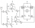
Sir, I'm Posting the circuit again... The circuit works well on no load but moment i connect the load one PNP mosfet gets hot and trips the supply. Is there something wrong with the configuration?
I too changed it to pnp, but the circuits not working still. what do you mean when you say top mosfet has no dc path for gate? which software are you using for simulation...
I too changed it to pnp, but the circuits not working still. what do you mean when you say top mosfet has no dc path for gate? which software are you using for simulation...
In your circuit, if D3 is a 15V zener then the voltage at Q6 gate is always 15V above Q3 emitter, i.e never rises above about 19V. That means Q6 is permanently on (unless its Vgs turn-on threshold is unusually high).
In your circuit, if D3 is a 15V zener then the voltage at Q6 gate is always 15V above Q3 emitter, i.e never rises above about 19V. That means Q6 is permanently on (unless its Vgs turn-on threshold is unusually high).
Q3 emitter voltage can only change by about 4V. Re-consider how you will use that to switch Q6 on and off reliably and whether a more conventional gate driving arrangement would be better.
Q3 emitter voltage can only change by about 4V. Re-consider how you will use that to switch Q6 on and off reliably and whether a more conventional gate driving arrangement would be better.
I would suggest using dedicated off-the-shelf FET bridge driver ICs, such as the IR2110 or its brothers, particularly if you want to switch FETs at high frequency. A problem with your present circuit is that at 100kHz it likely won't be able to handle enough current (~1A or so) to charge/discharge the FET gate capacitances sufficiently fast to prevent over-heating. Your circuit also provides no dead-time to prevent shoot-through by ensuring that the top and bottom FETs never conduct simultaneously during their finite switch-over times.
 Facebook
 Google
 GitHub
 Linkedin