mosfet

Thread Starter

vultac

Joined Mar 2, 2009
142
hi guys ive tried... the gate drive works etc... wads suprising to me is... my input voltage is 16V, i need to buck down to 6V ya.... and.... when i use PMOS... it doesnt work.... i analyze the graph of the drain of the PMOs and realized that it pulls it up till 5V meaning having 0V it pulls it up till 5V, then it becomes a pulse with 1Vpp... and didnt turn on mosfet...

however, when i tested it with NMOS... it pull ups to 16V and +0v htherefore i can switch it on n off properly... any explanation wyhy? the nmos source is connected to the indcutor btw and drain is connected to the voltge...
 

Audioguru

Joined Dec 20, 2007
11,248
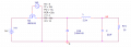
Again, please post the schematic of your P-channel Mosfet circuit and of your N-channel Mosfet circuit since we don't know what you are talking about.
 

Wendy

Joined Mar 24, 2008
23,801
This thread is close to a record. With so many references to schematics it is no wonder it is confusing! :eek:

I have to agree with something that was said a couple of posts ago, you are ready to try some concrete experiments. Try to draw a complete schematic, simulate it, and if it doesn't work as expected we'll analyze it together.
 

Thread Starter

vultac

Joined Mar 2, 2009
142
well, ive tried the PMOS... and it didnt work.... then i tried the NMOS (source not connected to ground)... it works...

this was done not in simulation but practical

PMOS gate pulse sent (+16V 0V) , analyzed ( 0.5vp_p) n no output
NMOS gate pulse sent (+16 0v), analyzed (14~16Vp_p), circuit wokring...

also input was (16V)

just need to know how to calculate the NMOS values for this type of configuration? some reasonable explanation abt the vgs and all?

thanks guys :(
 

Attachments

Audioguru

Joined Dec 20, 2007
11,248
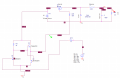
Your P-channel mosfet circuit is correct.
When the gate is +14V the same as its source then the Mosfet is turned off.
When the gate is 4V above ground so that the Vgs is 10V then the Mosfet is fully turned on. The inductor slows the charging of the 22uf capacitor and the drive duty-cycle from the Mosfet determines the output voltage.

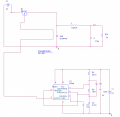
Your N-channel Mosfet circuit is completely wrong and I think we told you why a few hundred posts ago. Your Mosfet is a "source-follower". It turns on barely when its gate is +4V. But the gate is driven to only +3.7V by the ordinary 555. If you use a Cmos 555 then the gate will be +5V which is still much too low because the Mosfet needs a Vgs of 10V to fully turn on.
If the gate is +28V then the source will be +18V.
 

Thread Starter

vultac

Joined Mar 2, 2009
142
yeah,...i forget to mention... i used a gate driver circuit... meaning the gate can follow the voltage of my source for PMOS and for nmos is the gate can follow the drain... but for that... PMOS doesnt work NMOS works? whyyyy :( i thought both would work?

i mean cud u explain to me how to calculate the source follower "on and off" requirements... like Vgs needs to be??? etc?
 
Last edited:

kingdano

Joined Apr 14, 2010
377
yeah,...i forget to mention... i used a gate driver circuit... meaning the gate can follow the voltage of my source for PMOS and for nmos is the gate can follow the drain... but for that... PMOS doesnt work NMOS works? whyyyy :( i thought both would work?

i mean cud u explain to me how to calculate the source follower "on and off" requirements... like Vgs needs to be??? etc?

these things have been explained in prior posts - audioguru did a nice simulation demonstrating the on/off voltage behavior of a MOS device a while back in this thread
 

Thread Starter

vultac

Joined Mar 2, 2009
142
yeah ive read their post... but it was for a normal PMOS/NMOS... i just want to clarify wads the requirement to turn off a switch for a NMOS as a source follower and wads the requirement to turn it on... if we say Vgs... we wont know wad Vs would be? or when a nmos is a source follower we shud see the Vds? thanks
 

Audioguru

Joined Dec 20, 2007
11,248
Your schematic does not show a "gate driver circuit" so we do not know what it is or what it does. Maybe you connected it wrong.

You cannot understand that an ordinary Mosfet needs a Vgs of 10V to fully turn on.
The N-channel Mosfet needs its gate +10V more than its source to fully turn on.
The P-channel Mosfet needs its gate -10V less than its source to fully turn on.

A "follower" is a follower. You don't want a follower, you want a switch.
 

Wendy

Joined Mar 24, 2008
23,801
To continue AG's thought, this is why you are messing with a P-Channel MOSFET. A P-Channel can be a switch with a positive power supply.

N-Channel MOSFETs are better and more common, but some times you have to have the P-Channel version.
 

Thread Starter

vultac

Joined Mar 2, 2009
142
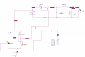
hmmm ok. ill post my schmeatic.. actually ive built it in a breadboard... using PMOS (theoretically it will work) it didnt.... but i changed it to NMOS (source follower) and use a gate driver and it works...

works in simulation too...the blue pulse is connected to the source of the NMOS. if it were switching it will be a pulse...
 

Attachments

Audioguru

Joined Dec 20, 2007
11,248
Why are you blowing up the IRFZ44 Mosfet with a much too high Vds voltage of 200V? Its absolute max Vds voltage is 60V.

Why are you blowing up the IRFZ44 Mosfet with a much too high Vgs as high as 200V? It absolute max Vgs is 20V.

Can't you read the spec's on the datasheet?
 

Thread Starter

vultac

Joined Mar 2, 2009
142
it was just a test, the real input is 16V, sorry for the confusion... but cud u explain to me why this circuit works?
 

Audioguru

Joined Dec 20, 2007
11,248
it was just a test, the real input is 16V, sorry for the confusion... but cud u explain to me why this circuit works?
If you are posting schematics that are not what you have, then I am wasting my time with you.

What is "cud"? The stuff that is chewed by a cow?
What is "u"? Underground?
What is "wud"? Is it messy like mud?
Are you only 12 years old?
 

Thread Starter

vultac

Joined Mar 2, 2009
142
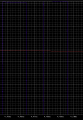
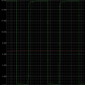
sorry. so let me start again. could you give me the proper explanation of why this source follower works or how does it work. hope you are willing to help. green is the pulse coming from the green voltage indicator on the schematic and red is the voltage output from the buck. This is what i have designed on the breadboard. Thanks. hope you can help.
 

Attachments

Audioguru

Joined Dec 20, 2007
11,248
Your Mosfet is a very hot heater instead of a cool switch.
Its input is 16V, its output is 12.19V and its current is (12.19V/22 ohms=) 554mA so it dissipates 2.1W of heat.

Instead, your Mosfet should be an on-off switch so that it stays cool without wasting power.
 

Thread Starter

vultac

Joined Mar 2, 2009
142
ok audio. I will try to explain what i am asking..... basically that circuit is a buck converter... and im using a NMOS source follower instead of other configuration. My question is, how do i calculate what value is needed on the gate to turn on/off the NMOS with this configuration?
 

Audioguru

Joined Dec 20, 2007
11,248
Why don't you understand that an ordinary N-channel Mosfet is fully turned on when its gate is +10V from its source?

I can't remember what output voltage you want. If it is +5V then the gate of the source-follower Mosfet must have a peak voltage higher than +15V which cannot be produced by a 555 that has only a +5V supply.
 
Top