i see i see thats why i observed in the lab as well.. it make sense now.. well i needa wait for monday to try it again and get back to guys! thanks everyone for sticking ur time with helping me !
using mebe something to put into the input? like for eg 5V to the input will give the first +19V, +9V
4V will give +18V +8V and so on?
i know what im trying to ask is confusing because i dont really know how to ask it! Lol.... i need to know whether there are any op amp with no voltage limits.... that allows me to set an on pulse with a range of 19V ~ 10V and off pulse of 9V~0V
I think you are asking for a circuit to produce a pulse? Correct?
There are a lot of high voltage op amps out there with decent specs. The term "no voltage limits" is vague and inaccurate, there ain't no such thing.
I was just experimenting with a new (to me) op amp, the NJM4565. It has a power supply spec of ±4VDC to ±18VDC. It would probably work for your application, since the term ± is slightly misleading. The actual max voltage of this op amp is 36VDC. Like most op amps of this class, it can not reach the positive power supply voltage or the negative supply voltage.
You may be better with a comparator (which is not an op amp) such as a LM393 or LM339.
This seems to be a better than average op amp, and I was able to pick some up for 35¢ each.
You posted while I did. The best answer I can give is read the spec sheet. Someone else can probably give a better answer.
ok i will read the spec... because what im dealing with right is that for my buck converter... my source voltage would vary between 0V~18V..... which means i need a Vg which can turn off in the range of lets say 0~18V and turn on at....-10V~8V... hope u get what i mean....
well my 555timer is producing the pulse within the range of +0V to +5V but i need some sort of circuit which can boost the output from the 555timer....so the range can vary... eg
555timer produce 0V~5V ... (circuit) output +14V ~ +4V because Vs = 14V
or 555timer produce 0V~5V ... (circuit) output +15V ~ +5V because Vs = 15V
so i can turn on and off my mosfet.... im looking at gate driver circuit... but i doubt that i can limit the voltage... sigh..
to clear up what im trying to say is that.. from the 555timer i can output any voltage till +0V to +18V for the high pulse... however for the low pulse i dont know how i can limit it so i can control it between maybe 0V ~ 8V to switch off the mosfet...
well for that roject u were using comparator and the other one i dont know what it is hahaha... but right now i have my 555timer producing a pulse for me... all i need now is to find a way to limit the low side voltage... well if i used zener it would work for one Vs.... but in my application my Vs is varying so i need to find a way to vary the voltage limit of zener diode :/
Just remember, the 555 was an example, because it has something called a totem pole output (I haven't seen that phrase in decades). It will connect to both Vcc (minus a little voltage) and ground. There are lots of ways to do this. I pick the 555 because it is simple, really simple, but you don't have to limit yourself.
I'm going to come out with a new switching regulator for that other thread of mine. No telling if it will work, but then, I draw and then check assumptions. It drives some folks crazy, but it is how I work. Occasionally I flop big time, and occasionally it works.
wire two zeners in parallel - each connected to the GND pin - one zener to produce the 8V pulse you want and one for the 19V pulse.
use the zeners in place of the resistors in teh LM317 example circuit
i am not completely familiar with the design anymore, or the thread so some of the details may be off - but the idea is sound.
as you want the FET gate to see 8V you would turn on one BJT and leave the other off
if you want the FET gate to see 19V you would turn on the other BJT and turn off the prior one.
this is a tricky method, and may not make immediate sense, but if you have found that varying the zener gets the job done, you can digitally select one of two (or more) zeners in a similar method to the LM317 example circuit.
yah i read about totem pole thing and its just :S to me... so yah LOL~ i want to keep my circuit as simple as possible.
king:
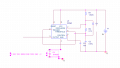
my schematic is on post #148... and can i apply the LM117, on the place where i place the zener diode? i dont really get how the circuit works tho..k lets say i have 4 zener diodes .... Z1 = 3.7V , Z2 = 4.5V, Z3 = 6V, Z4 = 8V... how can i tell the opamp which 1 to choose?
actually king for the output high i dont think its a problem i can always use an op amp to manipulate it... but the output low... i need the zener to limit it... like Z1~Z4...i need to choose 1 depending on the voltage of my converter..
or are there any component out there that allows me to program it so that let say if i connect 3 zener in parallel....den if its 6V ill send a pulse so that diode will condcut the other 2 will be off and so on?
A Mofset that needs a Vgs of 10V to turn on completely has a max allowed Vgs of 20V. So instead of switching the Vgs then simply use 12V to 15V all the time.
thanks...but how do i program it? it doesnt say much on the data sheet? so meaning for that IC i can have different values of voltage? and switch them on whenever i need a certain zener diode voltage? yes?
yeah but my Vsource will vary from 0~18V.... thats how my experiment is.. .. if its fixed it wud be simple..
i think i need a switch that will allow me to choose the diffrent zener voltage diodes rating depending on which 1 i want... like mebe if i put in 5V it will gie me Z1, 4V for Z2.... any idea? wwad ic are ther?
Low voltage zener diodes work poorly but a 2.7V zener diode should not be more than 3.0V if its current is a little too high or be less than 2.4V if its current is a little too low.
What is the rated current of your zener diode but if you didn't look at its datasheet then what is its part number so we can look at it?

 Facebook
 Google
 GitHub
 Linkedin

 !
!