mosfet

Wendy

Joined Mar 24, 2008
23,801
Odd thing about 741 (which is not a great choice for any design) and LM324 (which is better only because the power supply requirements are well defined and very wide).

When a op amp specifies 1Mhz freq response this is a unity gain number, the gain of the op amp is 1 no matter what the resistors are. Transistors have something similar.

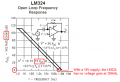
From the unity gain point going down in frequency the gain typically goes up 20 db. On a logarithmic graph it is very linear. So at 100KHz the gain is 10 (20db), and around 100 (40db) at 10KHz. The max gain is at DC (around 120db, or a gain of 1,000,000), which is very useful in it's own right. See the graph on page 6 of the datasheet attached.

There is another spec that affects freq response with op amps, and that is slew rate. This is the rate of change for the output. It is usually linear, and is measured in v/sec. For the LM324 this is somewhere around 0.6V/µs. While this sounds fast think in terms of a 12V power supply. 12V ÷ 0.6V is 20µs, the time it will take the op amp to switch between the two rails.

If you want fast switching speeds you need a comparator.
 

Attachments

kingdano

Joined Apr 14, 2010
377
Kingdano/AudioGuru:
Hmm but i saw the datasheet for 324 it says bandwidth 1Mhz? which parameter should i see so that i can get a clean 50Khz ~ 100KHz frequency? Or could you receommend me some OP AMPS which is good and inepensive for this.

Audioguru:

For my schematic... its just an "ideal" 555 timer.... the one im using in practical is a CMOS TS555CN timer....not sure about the load resistance... i connect it directly to the gate of my PMOS...and yah i used an oscilloscope btw... sorry for the confusion :)..

Hope to hear from you guys again soon...

P/S : Im trying to use the OP-AMP to boost the output voltage of the 555timer...so it can trigger the mosfet on/off....
The gain bandwidth is a product term, not simply the frequency at which the op-amp operates perfectly.

Look closely at the datasheet curves for frequency response and slew rate based on input voltages - you will likely see that you are not in the "sweet spot" for the op-amp

the input impedance of the PMOS will also be on the datasheet, you may need to add a matching impedance resistor to ground at the output to match the high impedance, as you may be severely mismatched source to load in terms of resistance. this would account for the voltage being "dropped" at the wrong point.


edit: beat me to it bill
 
Last edited:

Audioguru

Joined Dec 20, 2007
11,248
Hmm but i saw the datasheet for 324 it says bandwidth 1Mhz?
If an LM324 has a 30V supply then its gain is 1 (like a piece of wire) at 1MHz. With a 15V supply is gain is 1 at 350kHz. Then its gain is 2 at 175kHz and its gain is 4 at 87.5kHz.
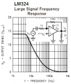
But its output cannot slew fast enough above 5kHz when its output swing is 14V. At 50kHz the output is triangle-waves of only 2.5V p-p.

For my schematic... its just an "ideal" 555 timer.... the one im using in practical is a CMOS TS555CN timer.
A Cmos 555 does not have enough output high current to discharge the high gate capacitance of a Mosfet. Then its signal to the gate is a low level sawtooth-wave. Use an ordinary 555 instead.
 

Thread Starter

vultac

Joined Mar 2, 2009
142
i would like to ask u guys one question abt mosfet.... if im using my buck converter..and i want to test the on and off voltages that will trigger my mosfet...... can i use just a DC voltage on the gate? FOr eg. when we discuss my mosfet would off at 19V and on < 9V.... if i use a DC voltage of 19V to the gate i should be able to observe that theres no voltage on the output?...am i right? then if i keep adjusting till mebe around 9V dc i should see a voltage on my output now ya? since its on? is this correct?
 

Wendy

Joined Mar 24, 2008
23,801
I'm not quite sure what you're asking, but I think you are talking about using the MOSFET in linear mode. The two most efficient (in wattage) states for any transistor (MOSFET, BJT, it doesn't matter) is on or off. In these conditions no wattage is generated. If you run the transistor in a linear mode it gets hot, sometimes quite hot.

This is why SMPS is so popular and efficient.
 

kingdano

Joined Apr 14, 2010
377
bill i think he was asking if he replaced the 555 timer with a dc source and manually swept voltage from 19 to 9V if he could see the output voltage on the MOSFET switch change.
 

Thread Starter

vultac

Joined Mar 2, 2009
142
yes guys... ive simulated it... and i get the on/off threshold voltage... unfortunately i cant get hold of a normal 555 timer.. only cmos 555 is available... and im planning to use an opamp to amplify the voltage.... the higher the slew rate V/S the btter the output i will get isit? like for eg 10V/us against 1V/us... which 1 is better? btw burnt a resistor today when i test my mosfet loL~
 

Audioguru

Joined Dec 20, 2007
11,248
The lousy old LM324 opamp is much too slow to amplify the low level from your Cmos 555. Its output is a low level triangle-wave because it cannot slew its output fast enough.

The triangle wave causes the Mosfet to be linear all the time which makes it extremely hot. If you use an "ordinary" 555 then the circuit will work perfectly without an opamp.
 

kingdano

Joined Apr 14, 2010
377
The lousy old LM324 opamp is much too slow to amplify the low level from your Cmos 555. Its output is a low level triangle-wave because it cannot slew its output fast enough.

The triangle wave causes the Mosfet to be linear all the time which makes it extremely hot. If you use an "ordinary" 555 then the circuit will work perfectly without an opamp.

i have a senior EE i work with who says that "any idiot can do it for a dollar but a genius can do it for 50 cents"

i think he probably uses a lot of LM324 op-amps :)


i say, pick the right device for the application - and tell the budgeting people to cram it.


also - very nice post

you certainly know your op-amp circuits well, i am working on improving my analog circuit skills and understanding - any tips - reading? simulating?
 

Thread Starter

vultac

Joined Mar 2, 2009
142
bill and king....

dont really understand....

audio:
....er...where in the datasheet does it says like 15V gain = 1 , f=1Mhz etc?


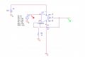
I only have 555cmos available to me... will try to order if possible...but at the mean tme... i found an opamp which is available and i have it its model is LT355N (WHat does the N means????) because the datasheet i found has no N and i saw it has a high slew rate... i will attach it... I used orcad to simulate it using the LT355 part... and amazingly it gives quite a nice output (green).... input is just a normal square wave +3V to 0V....the problem is that... i dont relaly understand the connection.. the V+ on top... and the gain...its not the same as a normal op amp :/.. i observed that when i change the Vdc for eg 18V to the top of V+ op amp i get 16V output... and the Vpeak to peak depends on the gain below... hmm???

sorry its lengthy! hope to hear from u all soon :)
 

Attachments

Audioguru

Joined Dec 20, 2007
11,248
you certainly know your op-amp circuits well, i am working on improving my analog circuit skills and understanding - any tips - reading? simulating?
I used a lousy old 741 opamp once. It was noisy (hiss) and did not produce high audio frequencies. I learned about its problems and never used an LM324 or LM358 opamp that have the same problems and more.

I learned a few things in university, a few more things from electronics magazines, data books and ordinary books, more things from the engineers in my first job at Philips and many more things by making my designs and testing them.
 

Thread Starter

vultac

Joined Mar 2, 2009
142
guys any idea why i keep burning my resistor .... when my gate i havent put in any pulse... just the Source of mosfet.... and BOOM! my L = 2mH , R = 30k, C = 22uF f = 40k current assumed was 0.23A
 

Audioguru

Joined Dec 20, 2007
11,248
where in the datasheet does it says like 15V gain = 1 , f=1Mhz etc?
The datasheet for every opamp has a frequency response graph. They also show Large Signal Frequency Response that shows that a poor slew rate causes the output level to drop at and above a certain frequency when the output becomes a triangle-wave.

i found an opamp which is available and i have it its model is LT355N (WHat does the N means????)
There is no LT355. But there was (it is discontinued) an LF355. The "N" is a plastic dual-inline package as shown on its datasheet.

The LF355 will not work in your circuit because its inputs do not work if they are within 5V to the negative supply which is ground in your circuit. The datasheet lists the minimum allowed Input Common-Mode Voltage Range as being -10V when the negative supply is -15V. A graph shows the "typical" Negative Common-Mode Input Voltage Limit to be affected by temperature and is about 2V more positive than the negative supply.
So since your negative supply is ground then the inputs must be at least +2V to +5V.
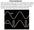
Also the inputs probably cause the "phase inversion" problem when their voltage is too low like it is in your circuit. You can fix your circuit if you bias the non-inverting input at half the supply voltage and capacitor-couple the input signal and couple a series capacitor to ground to the 1k feedback resistor.

i observed that when i change the Vdc for eg 18V to the top of V+ op amp i get 16V output...
That is normal. The output of the opamp has darlington emitter-followers with a 2V loss. With your 18V supply, the output will be high at about +16V and will be low at about +2V.
 

Attachments

Thread Starter

vultac

Joined Mar 2, 2009
142
ok guys thanks for the opamp help... but i just found an older version of 555timer... it allowed me to trigger my mosfet... however there is one thing im still not quite clear about....

Let say the source of my mosfet is connect to a DC of 14V , Vs = 14V
and Vgs to on is -10V, so Vgs = Vg - Vs and Vg = Vgs + Vs = 4V... this 4V....needed to turn on my mosfet.... what im not clear about is what is the range that my mosfet will be on? isit anything less than 4V? or is there a limit like 2V?

To off, the same case...im abit blur... Vgs = 0 and Vg = Vs = 14V... but whats the range that it will remian off? mebe 12V < Vg range < 14V ? Im not sure..

and for the resistor ya... i think i know why... my power rating for resistor is 1W only lol~ im going to find a power resistor..

thanks guyz :D
 

Ghar

Joined Mar 8, 2010
655
The number you're looking for is the MOSFET threshold, which is between 2V and 4V.

So, the PMOS will remain fully off with Vgs between 0 and -2, possibly -4, depending on the particular FET you have.
Any Vgs higher than that and the PMOS will be on, however the higher Vgs is the lower its resistance and the more current it allows.
 

Ghar

Joined Mar 8, 2010
655
Higher Vgs gives longer switching times... only an issue at very high frequency switching which you're not doing.

I think you're missing the point, it's not a 'higher current' it's a simply a better on-switch with a higher Vgs.
When I said 'allow current' I meant that near the threshold the FET can only conduct milliamps or so, it's a dreadful switch at that point.
 
Top