mosfet

Thread Starter

vultac

Joined Mar 2, 2009
142
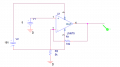
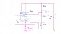
for the op-amp; isnt the vpulse the supply? ive tried changing V2 to 5V and also changing it to Vdc... i dont get the expected non-inverting op amp...

For the 555timer.. i didnt have much time yesterday... but when i finish constructing it on the breadboard... when the DC voltage was swithed to >5V... my output saturates at approximately 6V even with 15V Vcc supply to the 555timer....
 

Audioguru

Joined Dec 20, 2007
11,248
oh is the +V and -V power supply? on the diagram :S
Pins 4 and 11 are the power supply pins on the LM324.

The datasheet for the 555 shows that the output high voltage is typically 1.3V less than its positive supply voltage when its load current is nothing. Its output high is typically 1.6V less than its positive supply when its load current is 100mA.
 

Thread Starter

vultac

Joined Mar 2, 2009
142
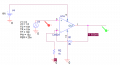
ive tried LM675 (attached) with the configuration shown, the output shows 15V...for LMC324 it doesnt work..actually im abit blur right now 3AM here... i think i will sleep now n wake up n re-read what uve written ><! thanks!
 

Attachments

Audioguru

Joined Dec 20, 2007
11,248
ive tried LM675 (attached) with the configuration shown, the output shows 15V...for LMC324 it doesnt work..
You started with an LM324 without a power supply. Then you used an LM675 power opamp and an LMC324 with their power supply floating.

Opamps do not work if their power supply is floating, it must be referenced to the circuit's ground by having a positive supply and a negative supply or ground if the opamp doesn't need a negative supply.
 

Wendy

Joined Mar 24, 2008
23,801
The output voltage of an ordinary 555 reaches as high as 1.3V less than its supply voltage. Then your supply voltage for your 555 is 7.3V.

If you look at post #86 I showed a CMOS 555 (7555). Some of the drawings I've used a 555, so there is a reason for the confusion. I have mentioned several times that the CMOS version is better than the conventional 555 for this application.
 

Thread Starter

vultac

Joined Mar 2, 2009
142
hi guys,

Ive simulated it using an opamp 635 as mentioned.. however it seems that my frequency from 555timer might be too high its 50Khz... and i read something called the GATE DRIVE.... which can used to boost the output of the PWM... anybody has any idea how i can use that??? im reading it but i dont quite get it :/
 

Audioguru

Joined Dec 20, 2007
11,248
The gate of a Mosfet has a fairly high capacitance. It takes a lot of current from a "gate driver circuit" to quickly charge and discharge the capacitance.
The output of an ordinary 555 has a max allowed current of 200mA which can drive older lower capacitance Mosfets at 50kHz but not newer Mosfets that have higher capacitance.
 

Thread Starter

vultac

Joined Mar 2, 2009
142
any suggestions on how i can boost the pulse coming out from the 555timer? Its fixed at around +3V and 0V..... and like i say before i need 16V and < 9V to turn off mosfet :(... need suggestions..
 

Audioguru

Joined Dec 20, 2007
11,248
There is something wrong with your 555 oscillator that is causing its output to be too low.
I don't know which page of this thread has the schematic that you are talking about.

I think you want to drive a P-channel Mosfet that has a 16V supply. Then you want its gate to be +16V when it is turned off and be <+9V when it is turned on. But an ordinary Mosfet needs its gate-source to be 10V so you want the gate to be +6V when the Mosfet is turned on.

For the 555 to produce an output low of +6V then it needs a 6V zener diode from its ground pin to ground. Its positive supply should be +17.3V so that its output high is 16V.

Please post your latest schematic.
 

Thread Starter

vultac

Joined Mar 2, 2009
142
well, my schematic is working.... i just tried building it... tkaing the components etc... and building it into the breadboard.. ive used the oscilloscope to test the output waveform of the 555timer... it gives around 2.3 ~ 5V..... im using TS555CN model... ive changed my design slight by adding a current mirror (which i will use a microcontroller to control the voltage souce of the current mirror to vary the DUTY cycle.) ill post the schematic in a bit afte ri restart my pc... the schematic works... but in real life it doesnt ;(! it saturates at aoorund 6V, the output of the 555timer even when i use 16V input...
 

Thread Starter

vultac

Joined Mar 2, 2009
142
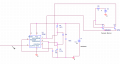
heres the schematic..... it works on simulation if i change the 555timer input Vcc to 16V...output will be somewhere there.. but in reality ;(!!!
 

Attachments

Thread Starter

vultac

Joined Mar 2, 2009
142
basically my whole circuit has got a buck .... and im using the 555timer to trigger it.... at the same time i will be programming a pic controller (now acting as the voltage of the current mirror) so that the voltage varies and i cud control the duty cycle of the 555timer.. however... my output of 555timer in reality only gives an output of 3v

can anyone show me the connection for gate driver? ...
 
Last edited:

Thread Starter

vultac

Joined Mar 2, 2009
142
thats odd... ive tried adjusting the supply to 16V... but it doesnt give an output of 14.7... it saturates at 3~4V........maybe ill go n check it again tomorrow. thanks....will get back to u soon... at the mean tim if my timer PWM output cudnt output enough voltage what do you think is best for me to boost the PWM output so i can reach 16V?
 

kingdano

Joined Apr 14, 2010
377
likely the distortion is due to operating at too high a frequency

if you slow down the oscillations and the output cleans up you will know you need an op-amp with a better bandwidth response than what you are using.
 

Audioguru

Joined Dec 20, 2007
11,248
thats odd... ive tried adjusting the supply to 16V... but it doesnt give an output of 14.7... it saturates at 3~4V........maybe ill go n check it again tomorrow.
Do you have an ordinary 555 or do you have a Cmos 555?
What is its load resistance?
Please post the schematic.

If it is an ordinary 555 and its load resistance is very high then its output high should be +14.7V if its supply is 0V and +16V. If its load is 144 ohms or more then its output high should be +14.4V.

You need an oscilloscope to see the output high voltage, not a meter.

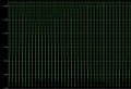
Hey guys was wondering how can i "smooth" the output coming out from the opamp? my input is a square wave..
The PER might be its period for each cycle. Then a PER of 20us is a frequency of 50kHz which is much too high for a lousy old slow LM324 opamp. It has trouble above 2kHz.
But your SIM program doesn't know about the slow speed of an LM324 opamp.
 

Thread Starter

vultac

Joined Mar 2, 2009
142
Kingdano/AudioGuru:
Hmm but i saw the datasheet for 324 it says bandwidth 1Mhz? which parameter should i see so that i can get a clean 50Khz ~ 100KHz frequency? Or could you receommend me some OP AMPS which is good and inepensive for this.

Audioguru:

For my schematic... its just an "ideal" 555 timer.... the one im using in practical is a CMOS TS555CN timer....not sure about the load resistance... i connect it directly to the gate of my PMOS...and yah i used an oscilloscope btw... sorry for the confusion :)..

Hope to hear from you guys again soon...

P/S : Im trying to use the OP-AMP to boost the output voltage of the 555timer...so it can trigger the mosfet on/off....
 

Attachments

Top