mosfet

kingdano

Joined Apr 14, 2010
377
As a general rule of thumb, the device should never be driven to its absolute maximum rating.

You should in fact, look for the rated Rds(on) Vgs voltage and use that, in addition to the Vgs threshold voltage as the drive voltage for the Vgs differential.

in this case 10+4 = 14VDC

I said 15VDC because i like to play it safe, and not teeter on the edge of the specification - provided i dont infringe on the ab max rating.
 

Thread Starter

vultac

Joined Mar 2, 2009
142
ok thanks... i get it now.... but for PMOS...... why will it work? I don understand y wont my NMOS work..... i mean if i remove the 7404... it will still work ya? given that the 555timer can output at least 15V to the gate? am i right?
 

Wendy

Joined Mar 24, 2008
23,801
I'm not sure what you are after, but a 555 is also a single chip inverter. For driving pMOS you will need a CMOS 555 though.
 

kingdano

Joined Apr 14, 2010
377
the 555 CAN supply 15 (actually 13.5 VDC if you read the datasheet) to the gate of the NMOS device.

however, it is not the Vg which is critial, remember, it is the Vgs.

Since the drain voltage is at 30V you need to have at least 45V on the gate to have a full turn on. Otherwise you have a source-follower configuration, not a switch, which is what you are after.

That is why it wont work.
 

Audioguru

Joined Dec 20, 2007
11,248
Your N-channel Mosfet is spec'd to turn on very well when its gate to source voltage is 10V. A 555 can supply 10V when its supply is 11.3V so I suggested that you use a 12V supply for the 555 and for the Switched Mode Power Supply circuit.

You want the Mosfet to pull up so a P-channel Mosfet should be used. An N-channel Mosfet has its drain go down to ground when it turns on but can be used if you change everything in the SMPS around.
 

Wendy

Joined Mar 24, 2008
23,801
Actually for a series pass element in a positive power supply you need a P-channel, you have a N-Channel. Several folks have pointed this out, such as Audioguru and kingdano.

All the drawings I have show the N-Channel MOSFET connected with source to ground.

****************

I started this post over an hour ago, and got involved in a house project. Oh well.
 

Thread Starter

vultac

Joined Mar 2, 2009
142
to billmarsden:
isit possible to give me some model of cmos 555 timer?

to kingdano:
how do u know that the drain voltage is at 30V?

to audioguru:
can you define the term pull up? and wad role does the inverter plays?


I really appreciate the help guys. i know im asking v basic questions but ya....im not to familiar with electronics :(
 

Audioguru

Joined Dec 20, 2007
11,248
"Pull up" means that the output of the Mosfet goes up (positive). The drain of a P-channel Mosfet goes positive and the drain of an N-channel Mosfet goes down to ground.

I think the inverter is needed because your very simple PWM control of the 555 does not go from a very narrow pulse to a very wide pulse because one diode is missing.
 

Wendy

Joined Mar 24, 2008
23,801
A CMOS 555 is pretty close to a conventional 555, most cases they are interchangeable.

A CMOS 555 doesn't have nearly the same drive, but at higher power supply voltages it approaches that of a 555. At 2V it is less than 1ma in many cases.

A standard 555 does not go rail to rail (rail to rail refers to the power supply rails, and the ability to reach those voltages), while a CMOS does this quite nicely. As it turns out, this ability is important to drive a p-channel MOSFET.

Radio Shack sells the TLC555, the TI version of a CMOS 555. I tend to use the 7555, another version, though in my articles I use the Radio Shack part (but sparingly, Radio Shack charges more and I do occasionally burn them out).

Bill's Index

The 555 Projects

My Cookbook

Want a 555 inverter?

555 Schmitt Trigger
 

kingdano

Joined Apr 14, 2010
377
to billmarsden:
isit possible to give me some model of cmos 555 timer?

to kingdano:
how do u know that the drain voltage is at 30V?

to audioguru:
can you define the term pull up? and wad role does the inverter plays?


I really appreciate the help guys. i know im asking v basic questions but ya....im not to familiar with electronics :(
i just know that in your original post the scope probe read 30V on the output node, since the drain is at the output node, it must also be close to 30V.

a "pull-up" means to pull a node (drive a node - terminology is different at times) to a higher voltage potential.

a "pull down" means to pull or drive a node to a low potential, usually 0V/ground
 

SgtWookie

Joined Jul 17, 2007
22,230
You can use a standard BJT 555 to drive a P-ch MOSFET, if you use a 330 Ohm 1W pull-up resistor from pin 3 to +12v. The 330 Ohm resistor makes up for the ~1.3v drop due to the Darlington output. Note that you'll have about 430mW power dissipation in the resistor when the 555's output is low (P-ch MOSFET turned ON), but it's not too bad if your ON time is relatively short.
 

Audioguru

Joined Dec 20, 2007
11,248
An ordinary P-channel Mosfet has a max current of 0.25mA when its gate-source is 2V. A 555 output high is 1.3V less than the supply so an ordinary P-channel Mosfet will be turned off when its gate-source voltage is only 1.3V.
 

Ghar

Joined Mar 8, 2010
655
If you do not meet this criteria, the device is not acting as a switch, but it is acting as a follower - meaning that the source follows the drain voltage.
.
Not really, a source-follower has the source following the gate.
Similarly, an emitter-follower has the emitter following the base.
If the source follows the drain you have a good switch, since it's approaching a short.
 

Thread Starter

vultac

Joined Mar 2, 2009
142
wow thats alot of information for me to digest.... thanks u all...well im gonna change my model and attach it soon to let u guys see whether it is better or not... as i have seen from the help u guys gave me... basically my mosfet isnt connected correctly yes? because for NMOS the source should be grounded ya?

To audioguru:
in where should i place another diode? because i followed this model http://www.doctronics.co.uk/555.htm .... and what effect has it got on the inverter? and what does the inverter actually does...
 

Thread Starter

vultac

Joined Mar 2, 2009
142
well when i tried to change the connections with the nmos n pmos basically it didnt work... but how come for the fiel i attached.... why does it work? i dont get it... the source is not connected to gnd....

when i changed it to PMOS, instead i get 16V at the output which isnt what i want...
 
Last edited:

Ghar

Joined Mar 8, 2010
655
basically my mosfet isnt connected correctly yes? because for NMOS the source should be grounded ya?
You need to be careful here... an NMOS is easy to drive when the source is grounded but it's not a requirement for it to work.
In your circuit you have no option. The FET is where it is, if you want to stick with an NMOS you need to use a more complicated gate driver. The source and drain need to stay where they are.
 

Audioguru

Joined Dec 20, 2007
11,248
To audioguru:
in where should i place another diode?
There are many 555 circuits that use two diodes for a complete range of PWM. Your circuit has only a small range so the inverter is needed.
The circuits have an output from pin 3 or from pin 7.

what effect has it got on the inverter? and what does the inverter actually does...
With only one diode then the PWM from the 555 goes from 50% to near 100% or from 0% to only 50%. Yhe inverter swaps the results.
Two diodes allow PWM from almost 0% to almost 100%.
 

Attachments

Last edited:

Thread Starter

vultac

Joined Mar 2, 2009
142
To ghar:

Yes. I have tried to change to PMOS and it is not working... im still sticking with my intial design... but i need some guidance on the definition of pull up n pull down... i mean where can i read those? PMOS/NMOS i dont even know where to connect the resistor to.

To audio guru:
I havent read ur reply but i will reply after i read this. OMG WHat am i toking abt.. basically i just re-read ur previous post u say that i can still use NMOS changing the SMPS around could u guide me on this?

Thanks guys
 

Thread Starter

vultac

Joined Mar 2, 2009
142
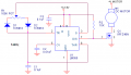
Hi my pin 7 says discharge, while pin 3, says output....

Another thing is when i remove the inverter and change the Vdc source off the timer. meaning its producing 200V. which is an impossible thing but i was just trying the circuit works properly. However, right now im still simulating the results using 5V.... which i think will take almost 30mins :S.... i really need some opinion on how to allow my Nmos to work as a switch? How can i ammend this design? Or probably the pull up/pull down thing? which i dont really understand... could you give me links or help me out to give me more information on it... thanks guys...

opps forget to attach
 
Last edited:

Ghar

Joined Mar 8, 2010
655
As I explained on the first/second page, to turn the NMOS on properly you need a gate voltage higher than the input voltage.
The alternative is to use an isolated gate drive, such as using a transformer.
 
Top