MOSFET switching for ADC.

Thread Starter

Legolas74

Joined Feb 19, 2015
5
Hi,
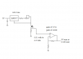
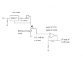
I want to measure the resistance of my load R4 that varies between 0.10 to 3.00 ohm.
I made a voltage divider R2, (R3+R4) and want to read the voltage with my ADC of my Arduino.
I use PWM at 100hz, and switch off U1 and switch on U2 & U3 during 200 microseconds each cycle.

XMM1 is my ADC connection, Source of U3 is connected directly to my ADC.
I'm not sure if you could do that, guess the source is not correctly grounded then?
But I don't know how to switch off the ADC connection when not measuring.

This circuit seems not to work since U2 always get blown.

I would appreciate any help to solve this.
Guess it may work with a P-channel MOSFET instead?
Is there any better way to measure the resistance of R4?

Thanks

/Anders


adc001.png
 

Reloadron

Joined Jan 15, 2015
7,887
The best way to go about this would be to build a constant current source as #12 has pictured. Run for example 10mA or 100mA through your Rx (Unknown) and measure the voltage drop across Rx with your ADC. A simple Google of "op amp current source" will bring up dozens of circuits. I would have the op amp drive a transistor. Using 100mA constant current for example would give you 10mV across 0.1 Ohms and 0.3V across 3 Ohms. You could make the current source switchable between 10mA and 100mA for low and high resistance values of Rx.

Ron
 

MikeML

Joined Oct 2, 2009
5,444
Two ways to measure resistance: Apply constant voltage and measure current, or
apply constant current and measure voltage.
 

Thread Starter

Legolas74

Joined Feb 19, 2015
5
Thanks a lot, for your suggestions.

I can't decouple my source from the power source (positive side), I don't know if that's going to be a problem?
The Arduino is sharing the ground with the same power source.

I'm reading and make some investigation of your suggestions, thanks a lot.

And do you know why my U2 MOSFET is blown in my circuit? Would like to learn from my failures. The MOSFET should handle up to 2.5A
 
Last edited:

ErnieM

Joined Apr 24, 2011
8,415
I can't tell what is the thing being measured is and what is the measuring thing.

Could you just show the circuit you are attempting to measure so we can see the initial problem? Include any conditions like when it is on or off.
 

Thread Starter

Legolas74

Joined Feb 19, 2015
5
I think this is what you suggest, now I have a constant current at 104 mA.
And I measure the voltage across the resistance to be measured, I need to amplify this voltage with an op amp to be able to measure it with my ADC.
But now I don't know how to measure it, because the ADC is measuring everything relative to ground, or?

adc002.jpg


ErnieM,
I have a load that is running in PWM 100hz, duty cycle varies from 5-90%
The load resistance varies from 0.10 - 3.00 ohm.
Circuit is just like below.

I have connected an interrupt on my Arduino for low PWM pulse, during this low state I want to measure the resistance of the load R2.
The Arduino is sharing the same power source, through a LDO - LP2950ACZ-5.0.


acd000.jpg
 

Thread Starter

Legolas74

Joined Feb 19, 2015
5
I can't disconnect/decouple my load (resistance to be measured) from the power source and mosfet - It need to maintain the second circuit in the last post.
I need to measure the resistance while the mosfet U1 is switched off in that circuit.
 

#12

Joined Nov 30, 2010
18,224
What I'm saying is that the 0.3 volts the (resistor under test) will use up can not defeat the gate operation of the mosfet. The, "L" in the part number indicates a logic level gate. I can't find the datasheet for that one, but 4.7 Vgs is usually more than sufficient for 0.1 amp.

Am I addressing your concern?
 

ronv

Joined Nov 12, 2008
3,770
You can't use a 358 kike that. The voltage on the inputs must be 1.5 volts below the power supply voltage.
 

ErnieM

Joined Apr 24, 2011
8,415
Stop what you are doing and look at ronv,'s post. High side current sense IC's. do exactly what you need to do: convert the voltage across that resistor to a ground referenced voltage, and amplify it too.

That gets you the voltage across an unknown resistor. To get the current I'd put another similar circuit in series, but with a known resistor so the current can be measured.
 
Top