Hi,
i am trying MOSFET switching circuit to switch milivolts voltage to volts but when i increase drain voltage resistor and MOSFET are heating what wold be the solution...
If the input signal only has 750mV then you should use a npn transistor to amplify the signal and the output to drive the P type MOSFET, and if the output only needs 3~5Vpp then you will need a voltage divider.
How much current you need from the output of MOSFET?
1)I want to drive 1Mhz transducer, current has not been specified in data sheet but transmitter burst pulse should have 3Vp-p to 5Vp-p.
2)when i provide 20v dc supply to the drain of MOSFET as shown in above circuit am getting output square wave of 2Vp-p but resister and transistor gets heated up.
3)am not getting more then 750mv because am getting this voltage from TX pin of TDC-1000 chip.
Hi,
i am trying MOSFET switching circuit to switch milivolts voltage to volts but when i increase drain voltage resistor and MOSFET are heating what wold be the solution...
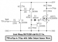
If the duty cycle of input signal is to narrow then it should be reduces the values of R2 and R3, the Imax ≅ 20mA, if you use the N MOSFET on the output then probably you can't get a 0V to 5V level signal.
Why you need to using 20V to be the power source, why not 12V or 5V?
If the duty cycle of input signal is to narrow then it should be reduces the values of R2 and R3, the Imax ≅ 20mA, if you use the N MOSFET on the output then probably you can't get a 0V to 5V level signal. View attachment 142565
Why you need to using 20V to be the power source, why not 12V or 5V?
Hi scott,
i tried with 5V and 12V for MOSFET circuit but it din't work out so i tried for 20v. Thanks for the circuit suggestion i will try out this and let u know the result.
Hi scott,
i tried with 5V and 12V for MOSFET circuit but it din't work out so i tried for 20v. Thanks for the circuit suggestion i will try out this and let u know the result.
If you using the circuit that your posted in the first post, the output voltage is quite high when the input is 0V then the output will be close to 20Vdc, for 12V is easy to make the MOSFET to turn on, but when you use 5V for the power source then you better to choose the type of Vgs has logic level = 4.5V or 5V.
Hi scott,
i tried the circuit without mosfet part that has attached but am not getting any wave form.
1)Is it k if i use BC557 pnp transistor in place of 2n3906 pnp transistor
Hi scott,
i tried the circuit without mosfet part that has attached but am not getting any wave form.
1)Is it k if i use BC557 pnp transistor in place of 2n3906 pnp transistor
Try to measure the c of Q1, if it still no any waveform then the problem could be R1(reduces it) or the input voltage too less to active the Vbe as the same that the Ib1 is too small.
Try to measure the c of Q1, if it still no any waveform then the problem could be R1(reduces it) or the input voltage too less to active the Vbe as the same that the Ib1 is too small.
I measured the voltage across collector of Q1 am getting waveform with 58mv there is a huge voltage drop after the transistor Q1 and across Q2 am not getting any waveform.
 Facebook
 Google
 GitHub
 Linkedin